
Novel all-optical fiber electronic current transformer and optical fiber wave plate

A current transformer and all-fiber technology, which is applied in voltage/current isolation, measurement of current/voltage, instruments, etc., can solve the problems of reduced measurement accuracy

Pending Publication Date: 2019-05-14
XUJI GRP +1
View PDF0 Cites 0 Cited by
  • Summary
  • Abstract
  • Description
  • Claims
  • Application Information

AI Technical Summary

Problems solved by technology

[0003] The purpose of the present invention is to provide a new type of all-fiber electronic current transformer and a fiber optic wave plate to solve the problem of reduced measurement accuracy due to the change in the size of the wave plate caused by temperature changes
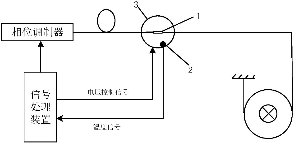
The present invention collects the temperature information of the wave plate body in real time through the temperature sensor, and transmits the temperature information to the signal control device. According to the temperature change, the signal control device outputs a control signal to control the wave plate size adjustment module, thereby changing the size of the wave plate body. Furthermore, a temperature compensation control is formed on the wave plate body, which compensates for the deformation of the wave plate caused by temperature changes and solves the problem of reduced measurement accuracy caused by changes in the size of the wave plate caused by temperature changes

Method used


Image

  • Novel all-optical fiber electronic current transformer and optical fiber wave plate
  • Novel all-optical fiber electronic current transformer and optical fiber wave plate

Examples


Embodiment Construction

[0015] The present invention will be described in further detail below in conjunction with the accompanying drawings.

[0016] The invention provides a novel all-fiber electronic current transformer, such as figure 1 As shown, it includes a fiber optic wave plate and a signal processing device, wherein the fiber optic wave plate includes a wave plate body 1, a piezoelectric ceramic 2 and a temperature sensor 3, and the piezoelectric ceramic 2 is configured to control and adjust the size of the wave plate body 1, and the temperature sensor 3 Used to detect the temperature of the wave plate body 1 , the output end of the signal processing device is connected to the temperature sensor, and the output end of the signal processing device is connected to the piezoelectric ceramic 2 . In circuit transformers, the signal processing device also controls the connection of the phase modulator.

[0017] The signal processing device controls the deformation of the piezoelectric ceramic 2 ...


PUM


Abstract

The invention relates to the technical field of optical fiber sensing, in particular to a novel all-optical fiber electronic current transformer and an optical fiber wave plate. The current transformer comprises the optical fiber wave plate and a signal processing device, wherein the optical fiber wave plate comprises a wave plate body, a piezoelectric ceramic and a temperature sensor; the wave plate body is fixedly attached to the surface of the piezoelectric ceramic through a physical or chemical method; the piezoelectric ceramic is used for controlling the size of the wave plate body; the temperature sensor is used for detecting the temperature of the wave plate body; the output end of the signal processing device is connected with the temperature sensor; and the output end of the signal processing device is connected with the piezoelectric ceramic. The temperature sensor collects temperature information of the wave plate body in real time and transmits the temperature information to a signal control device, and the signal control device performs output control on the piezoelectric ceramic, so that the size of the wave plate body is changed, temperature compensation type controlis formed for the wave plate body, and the problem that the measurement precision is reduced due to the change of the size of the wave plate caused by the temperature change is solved.

Description

technical field [0001] The invention relates to the technical field of optical fiber sensing, in particular to a novel all-fiber electronic current transformer and an optical fiber wave plate. Background technique [0002] Compared with traditional electromagnetic transformers, all-fiber electronic current transformers based on the Faraday magneto-optical rotation effect have many advantages such as large measurement range, high precision, and good insulation, and are increasingly valued by researchers at home and abroad. However, due to the linear birefringence of the optical fiber, the Verdet constant, and the quarter-wave plate of the optical fiber vary with temperature, the measurement accuracy in the full temperature range (-40-85°C) is reduced. Among them, the linear birefringence of the optical fiber is the Inherent in itself, related to the manufacturing process, it can be controlled by reducing the inherent birefringence of the fiber and annealing the fiber ring in ...

Claims


Application Information

Patent Timeline
IPC IPC(8): G01R15/24G01R19/00G01R35/02
Inventor 田志国池立江袁亮冉允喜孙振世张贺寄晓栋韩笑魏少鹏
Owner XUJI GRP
Learn More