A high-accuracy and compact drainage radar flowmeter

An accuracy and flowmeter technology, applied in the direction of liquid/fluid solid measurement, measurement device, engine lubrication, etc., can solve the problems of inability to obtain measurement data, failure to meet the drainage pipe network, high maintenance and maintenance costs, and achieve accurate measurement , Improve work reliability and use flexibility, measure the effect of no blind zone

Active Publication Date: 2022-07-26
无锡航征科技有限公司
View PDF6 Cites 0 Cited by
  • Summary
  • Abstract
  • Description
  • Claims
  • Application Information

AI Technical Summary

Problems solved by technology

The water quality in the urban pipe network is relatively complicated, especially the sewage pipes are often accompanied by debris and garbage. Generally, contact measurement equipment requires frequent maintenance and the maintenance cost is too high. The debris and garbage can easily affect the accuracy of the measurement data; use non-contact The non-contact measuring equipment can prevent debris from affecting the accuracy of the measurement, but it also has its own weaknesses. The water in the pipeline is often full. When the pipe is full, the use of non-contact measuring equipment cannot obtain accurate measurement data, and these measurements The equipment system is usually presented in the form of an independent water level meter, an independent flow rate meter, or a relatively large integrated system, and then the flow function in the pipeline is obtained by calculation. In the prior art, this integrated method to obtain the flow function has been impossible. It meets the requirements of the drainage network for small equipment and no blind spots in the function when submerged in water, and the volume requirements for small-diameter pipes are more obvious

Method used


Image

  • A high-accuracy and compact drainage radar flowmeter
  • A high-accuracy and compact drainage radar flowmeter
  • A high-accuracy and compact drainage radar flowmeter

Examples


Embodiment Construction

[0040] The specific embodiments of the present invention will be described below with reference to the accompanying drawings.

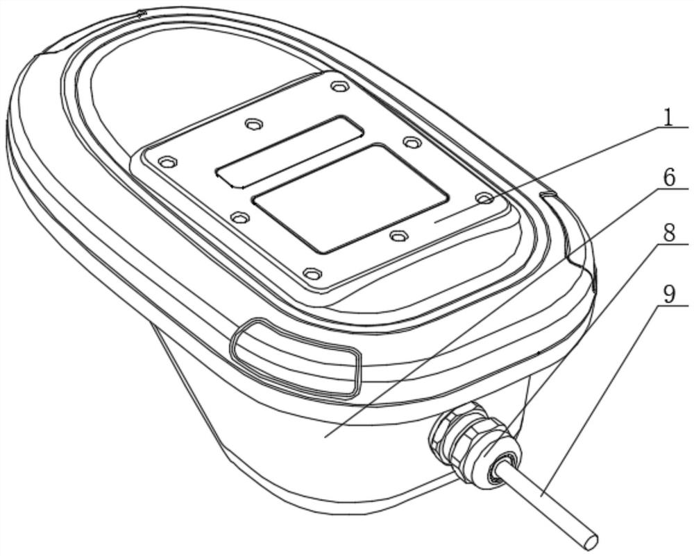
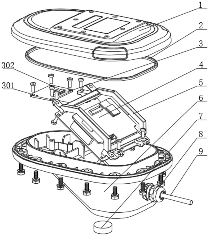
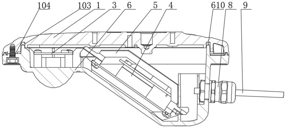
[0041] like Figure 1-Figure 11 As shown in the figure, the high-accuracy and compact drainage radar flowmeter of this embodiment includes a lower cover 6, the top surface of the lower cover 6 is open, a cavity is arranged inside the lower cover 6, and a fixed Bracket 5, a radar speed measuring plate group 4 is installed on the fixing bracket 5 through fasteners, the radar speed measuring plate group 4 is installed obliquely, and a radar water level plate group 3 is installed on the lower cover 6 beside the radar speed measuring plate group 4 through fasteners, The radar water level plate group 3 is connected to the radar speed measuring plate group 4 through the cable, and the upper cover 1 is installed on the top surface of the lower cover 6 through the sealing gasket 2;

[0042] The top surface of the upper cover 1 is provided with a label groove ...


PUM


Abstract

The invention relates to a drainage radar flowmeter with high accuracy and compactness, comprising a lower cover, the top surface of the lower cover is open, a cavity is arranged inside the lower cover, and a fixing bracket is installed in the cavity , a radar speed-measuring plate group is installed on the fixing bracket through fasteners, the radar speed-measuring plate group is installed obliquely, and a radar water-level plate group is installed on the lower cover beside the radar speed-measuring plate group through fasteners. The radar water level plate group is connected with the radar speed measuring plate group through the cable, the upper cover is installed on the top surface of the lower cover through the sealing gasket; one end of the lower cover is also connected to the communication cable through the waterproof joint. The invention has compact and reasonable structure and convenient operation. By coordinating the installation of radar water level plate group, radar flow rate plate group and transducer between the upper cover and the lower cover, it becomes a highly integrated flowmeter, which can meet the requirements of use, and is especially suitable for small pipes. In pipes with larger diameters, the working reliability and flexibility of the flowmeter are greatly improved.

Description

technical field [0001] The invention relates to the technical field of flowmeter equipment, in particular to a drainage radar flowmeter with high accuracy and small size. Background technique [0002] At present, the monitoring equipment for water in the urban pipe network mainly includes two types: contact type and non-contact type. The water quality in the urban pipe network is relatively complex, especially sewage pipes are often accompanied by debris and garbage, etc. Generally, contact measurement equipment requires frequent maintenance and maintenance costs are too high, and debris and garbage can easily affect the accuracy of measurement data; use non-contact measurement equipment. The non-contact measuring equipment can avoid the impact of debris and garbage on the measurement accuracy, but it also has its own weaknesses. The water in the pipeline often fills the pipe. When the pipe is full, the use of non-contact measuring equipment cannot obtain accurate measuremen...

Claims


Application Information

Patent Timeline
Patent Type & Authority Patents(China)
IPC IPC(8): G01F23/284
CPCG01F23/284
Inventor 陈德莉曾波朱世平
Owner 无锡航征科技有限公司
Why Eureka
Try Eureka