Automatic change-over switch

An automatic transfer switch and turntable technology, which is applied to electric switches, power devices inside switches, electrical components, etc., can solve the problem of slow opening speed, breaking capacity is greatly affected by motor speed or manual operation speed, and double-position breaking cannot be realized. Electricity and other issues

Pending Publication Date: 2019-05-14
ZHEJIANG CHINT ELECTRIC CO LTD
View PDF19 Cites 4 Cited by
  • Summary
  • Abstract
  • Description
  • Claims
  • Application Information

AI Technical Summary

Problems solved by technology

[0006] However, the transmission mechanism of this type of automatic transfer switch generally adopts the principle of positioning mechanism. Although the positioning of three different positions can be realized, the opening speed is relatively slow, and the breaking capacity is greatly affected by the motor speed or manual operation speed. defect
[0007] There is also an automatic transfer switch, which is a single-chamber structure, the moving contact assembly is a single rotation center, and its transmission mechanism is an electromagnetic suction type, such as a Chinese patent, the publication number is CN102812531A, and the patent name is "power transfer switch". The transfer switch has a two-stage structure, that is, when the mechanism is powered, it can only choose the normal power supply or the backup power supply, and cannot realize double-position power failure, and the speed at which the contact begins to move is related to the speed of electromagnetic attraction

Method used


Image

  • Automatic change-over switch
  • Automatic change-over switch
  • Automatic change-over switch

Examples


Embodiment Construction

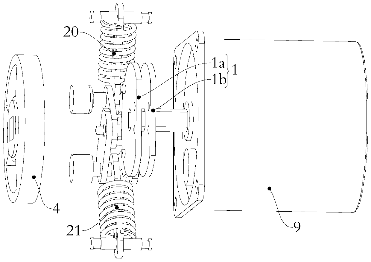
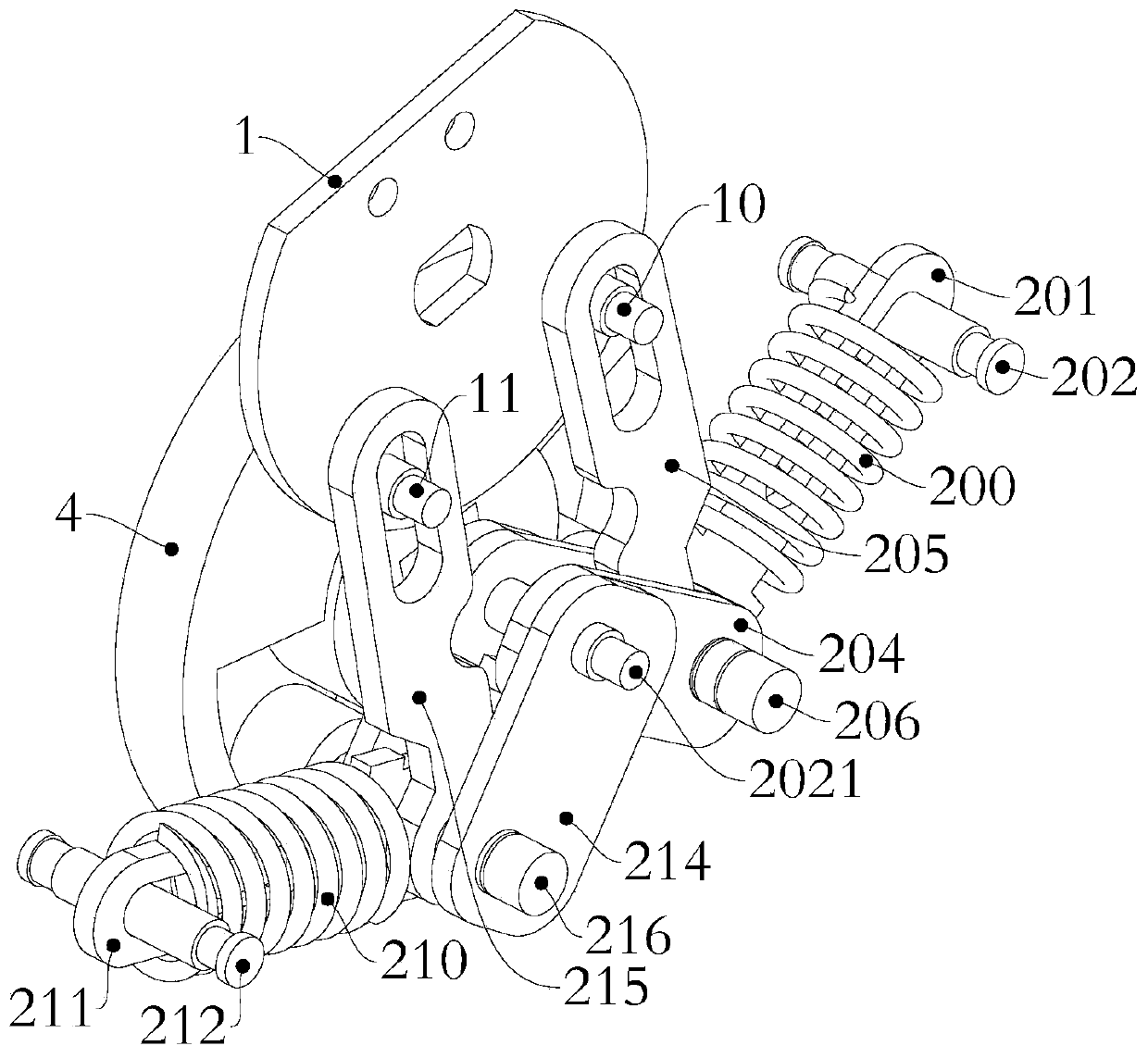
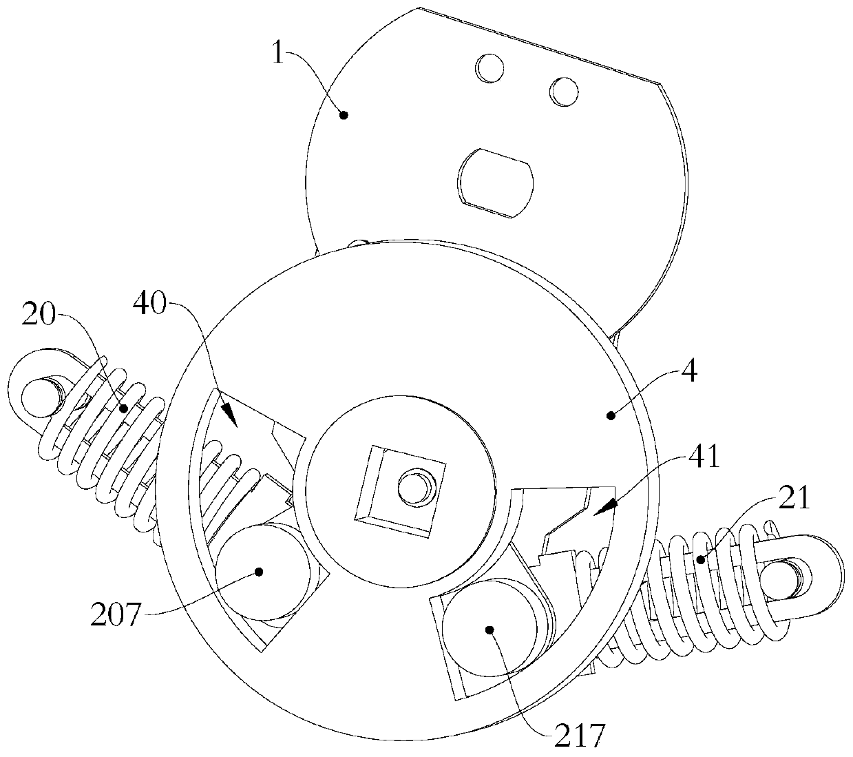
[0046] The following is attached Figure 1-11 The given examples further illustrate the specific implementation of the automatic transfer switch of the present invention. The automatic transfer switch of the present invention is not limited to the description of the following embodiments.

[0047] The automatic transfer switch of the present invention includes an energy storage operating mechanism, and the energy storage operating mechanism includes a drive plate 1, a connecting rod mechanism, a left spring damping mechanism 20, a right spring damping mechanism 21, a left drive shaft assembly 206 and a right drive shaft assembly 216 The drive disc 1 is connected to the link mechanism, and the link mechanism is respectively hinged with the left drive shaft assembly 206, the right drive shaft assembly 216, the left spring damping mechanism 20, and the right spring damping mechanism 21 one end, and the left spring damping mechanism 20 is in addition One end is pivotally set, the...


PUM


Abstract

The invention relates to the field of low-voltage electric appliances, in particular to an automatic change-over switch. When an energy storage operating mechanism is located at a second stable position, a driving disc rotates in the direction R1 under external force, and the driving disc 1 drives a left spring damping mechanism to enable the left spring damping mechanism to store energy through aconnecting rod mechanism; when the left spring damping mechanism swings to cross a first critical point, the left spring damping mechanism releases energy, and a left driving shaft assembly is drivento move in an accelerated mode, and a first power supply and a load are rapidly conducted, and the energy storage operation mechanism enters a first stable position; when the energy storage operatingmechanism is in a second stable position, a driving disc rotates in the direction R2 under external force, and the driving disc drives a right spring damping mechanism to enable the right spring damping mechanism to store energy through a connecting rod mechanism; when the right spring damping mechanism swings to cross a second critical point, the right spring damping mechanism releases energy,and a right driving shaft assembly is driven to move in an accelerated mode, and a second power supply and a load are rapidly conducted, and the energy storage operation mechanism enters a third stable position. Quick conduction of the switch can be realized, and the three-section operation of the switch can be achieved.

Description

technical field [0001] The invention relates to the field of low-voltage electrical appliances, in particular to an automatic transfer switch. Background technique [0002] PC grade automatic transfer switches currently on the market: [0003] 1. There is a double-chamber type, that is, the contact system of the normal power supply and the contact system of the backup power supply are located in two different chambers, such as a Chinese patent, the announcement number is CN202906563U, and the patent name is "a dual power supply switch" ; [0004] 2. There is also a contact structure with double rotation centers, that is, the contacts of the common power supply and the backup power supply have different contact rotation centers. For example, the Chinese patent, the publication number is CN103441008A, and the patent name is "Instantaneous parallel conversion structure of automatic transfer switch ", and the Chinese patent, the announcement number is CN203434032U, and the pat...

Claims


Application Information

Patent Timeline
Patent Type & Authority Applications(China)
IPC IPC(8): H01H9/26H01H3/30
Inventor 黄文体郭德鑫洪诗长
Owner ZHEJIANG CHINT ELECTRIC CO LTD
Why Eureka
Try Eureka