A cement pouring formwork pressing equipment
A formwork and cement technology, which is applied in the field of cement pouring formwork pressing equipment, can solve the problems of troublesome adjustment of sawing position, personnel injury, etc., and achieve the effect of simplifying operation, preventing personnel injury, and convenient and quick sawing.
- Summary
- Abstract
- Description
- Claims
- Application Information
AI Technical Summary
Problems solved by technology
Method used
Image

Examples
Embodiment 1
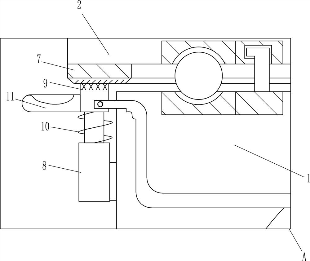
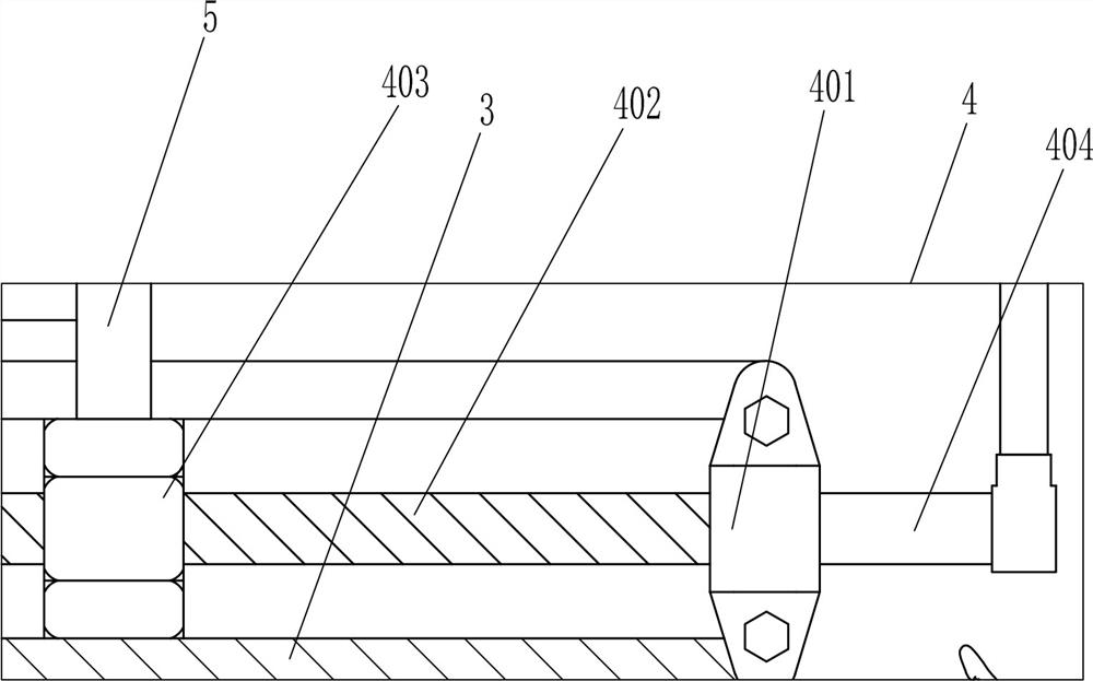
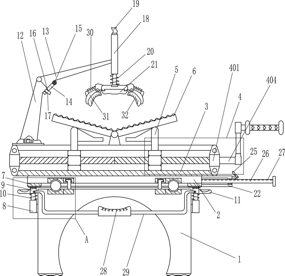
[0022] A cement pouring formwork pressing equipment, such as Figure 1-4 As shown, it includes a base 1, a mounting plate 2, a sliding frame 3, a moving mechanism 4, a moving rod 5, a placing plate 6, an annular rubber ring 7, a first telescopic rod 8, a pressing block 9, a first spring 10 and a first Push rod 11, the top of base 1 is rotatably connected with mounting plate 2, the top of mounting plate 2 is connected with sliding frame 3, and sliding frame 3 is provided with moving mechanism 4, and the parts of moving mechanism 4 are connected with two moving rods 5, and the moving The rod 5 slides through the top of the sliding frame 3, and the middle of the top of the sliding frame 3 is rotatably connected with two placement plates 6. The bottoms of the left and right placing plates 6 are respectively in contact with the tops of the left and right moving rods 5, and the bottom of the mounting plate 2 is connected. There is an annular rubber ring 7, the upper part of the left...
Embodiment 2
[0024] A cement pouring formwork pressing equipment, such as Figure 1-4As shown, it includes a base 1, a mounting plate 2, a sliding frame 3, a moving mechanism 4, a moving rod 5, a placing plate 6, an annular rubber ring 7, a first telescopic rod 8, a pressing block 9, a first spring 10 and a first Push rod 11, the top of base 1 is rotatably connected with mounting plate 2, the top of mounting plate 2 is connected with sliding frame 3, and sliding frame 3 is provided with moving mechanism 4, and the parts of moving mechanism 4 are connected with two moving rods 5, and the moving The rod 5 slides through the top of the sliding frame 3, and the middle of the top of the sliding frame 3 is rotatably connected with two placement plates 6. The bottoms of the left and right placing plates 6 are respectively in contact with the tops of the left and right moving rods 5, and the bottom of the mounting plate 2 is connected. There is an annular rubber ring 7, the upper part of the left ...
Embodiment 3
[0027] A cement pouring formwork pressing equipment, such as Figure 1-4 As shown, it includes a base 1, a mounting plate 2, a sliding frame 3, a moving mechanism 4, a moving rod 5, a placing plate 6, an annular rubber ring 7, a first telescopic rod 8, a pressing block 9, a first spring 10 and a first Push rod 11, the top of base 1 is rotatably connected with mounting plate 2, the top of mounting plate 2 is connected with sliding frame 3, and sliding frame 3 is provided with moving mechanism 4, and the parts of moving mechanism 4 are connected with two moving rods 5, and the moving The rod 5 slides through the top of the sliding frame 3, and the middle of the top of the sliding frame 3 is rotatably connected with two placement plates 6. The bottoms of the left and right placing plates 6 are respectively in contact with the tops of the left and right moving rods 5, and the bottom of the mounting plate 2 is connected. There is an annular rubber ring 7, the upper part of the left...
PUM
 Abstract
Description
Claims
Application Information
 - R&D
- Intellectual Property
- Life Sciences
- Materials
- Tech Scout
- Unparalleled Data Quality
- Higher Quality Content
- 60% Fewer Hallucinations
Browse by: Latest US Patents, China's latest patents, Technical Efficacy Thesaurus, Application Domain, Technology Topic, Popular Technical Reports.
© 2025 PatSnap. All rights reserved.Legal|Privacy policy|Modern Slavery Act Transparency Statement|Sitemap|About US| Contact US: help@patsnap.com