Automatic side wall separating mechanism of electric connector

An automatic separation and electrical connector technology, applied in the direction of self-propelled projectiles, weapon types, projectiles, etc., can solve the problems of poor separation effect of electrical connectors, and achieve the effects of high connection reliability, improved efficiency and convenient use.

Active Publication Date: 2019-05-17
杭州航天电子技术有限公司
View PDF7 Cites 1 Cited by
  • Summary
  • Abstract
  • Description
  • Claims
  • Application Information

AI Technical Summary

Problems solved by technology

[0004] The purpose of the present invention is to provide an automatic separation mechanism for the side wall of the electrical connector to solve the technical problem of poor separation effect of the electrical connector caused by the existing separation mechanism

Method used


Image

  • Automatic side wall separating mechanism of electric connector
  • Automatic side wall separating mechanism of electric connector
  • Automatic side wall separating mechanism of electric connector

Examples


Embodiment Construction

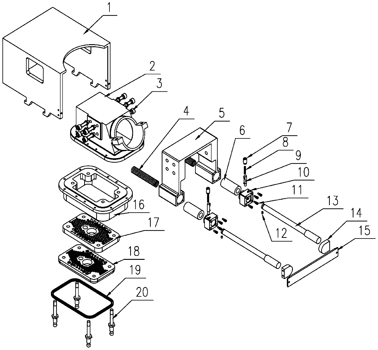
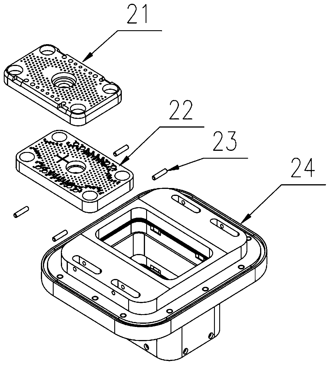
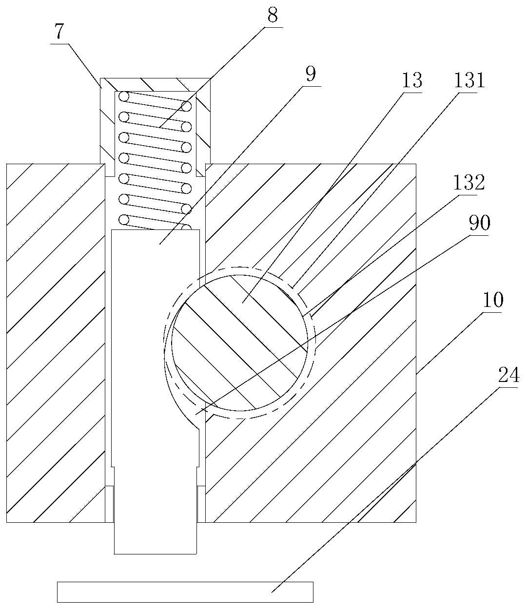
[0029] Such as figure 1 , figure 2 As shown, a side wall automatic separation mechanism of an electrical connector includes a plug and a socket, and the socket includes a socket housing 24 and a locking pin 23, and the locking pin 23 is arranged on the socket housing 24. The plug includes a shell 1, a plug cable cover 2, a fixing frame 5 and a plug housing 16, the shell 1 is provided with a cavity, the plug cable cover 2 is fixedly connected in the fixing frame 5, and the fixing frame 5 is arranged on In the cavity, the housing 1 is provided with an opening, the plug cable cover 2 is provided with threaded holes, the fixing frame 5 is provided with through holes, and the plug cable cover 2 is fixedly connected to the fixing frame 5 by bolts 3 Above, the plug cable cover 2 is fixedly connected to the plug housing 16, and the housing 1 is provided with a hook that cooperates with the locking pin 23; the fixing frame 5 is provided with a fixing block 10 fixed by screws 11 , th...


PUM


Abstract

The invention relates to an automatic side wall separating mechanism of an electric connector. The side wall automatic separating mechanism comprises a plug and a socket, wherein the socket comprisesa socket shell and a locking pin, and the plug comprises an outer shell, a plug cable cover, a fixing frame and a plug shell; the plug cable cover is fixedly connected in the fixing frame, and a clamping hook matched with the locking pin is arranged on the outer shell. The automatic side wall separating mechanism of the electric connector is characterized in that the clamping hook is arranged on the outer shell and the locking pin is arranged on the socket, when the plug and the socket can be plugged, only the downward insertion force needs to be applied to the outer shell, when the plug is incontact with the socket, a locking block is subjected to upward pressure, a pressure spring is compressed, when a groove is matched with a moving end, a guide rod moves leftwards under the acting force of a spring, the outer shell moves leftwards along with the guide rod, and when the clamping hook on the outer shell clamps the locking pin, the plug and the socket can be locked. The automatic side wall separating mechanism has the advantages of being capable of automatically separating along with elasticity, high in reliability and convenient to use.

Description

technical field [0001] The invention relates to a side wall automatic separation mechanism of an electric connector. Background technique [0002] In recent years, with the development of my country's weapons industry, a large number of high-precision pre-research strategic and tactical weapons have emerged. Higher-precision weapons require a high degree of control over the projectile before launch, and the launch system needs to monitor the projectile in real time. state until the model is ignited and takes off. [0003] The traditional separation mechanism generally adopts the axial separation method. There are mainly two types of installation methods at the connection part of the projectile. One is installed at the bottom of the projectile. The separation direction of this type of separation mechanism is on the same axis as the flight direction of the projectile. When the body is flying, it drives the separation mechanism to unlock the zipper, and completes the electrical...

Claims


Application Information

Patent Timeline
Patent Type & Authority Applications(China)
IPC IPC(8): F42B15/36
CPCY02T10/70
Inventor 张俊刘志郭广华管思阳梅武广
Owner 杭州航天电子技术有限公司
Why Eureka
Try Eureka