
Direct-current electric automobile power battery protection device and work method thereof

A technology for power batteries and electric vehicles, applied in electric vehicles, electrical devices, vehicle components, etc., can solve the problems of reducing the reliability and safety of system protection, limited short-circuit current tolerance, and high prices of power electronic switches. Improve reliability and economy, protect safety, overcome susceptibility to damage

Active Publication Date: 2019-05-21
XI AN JIAOTONG UNIV
View PDF4 Cites 6 Cited by
  • Summary
  • Abstract
  • Description
  • Claims
  • Application Information

AI Technical Summary

Problems solved by technology

Therefore, the extremely large short-circuit current is likely to cause damage to the power electronic switch, which is caused by the limited ability of the power electronic device to withstand the short-circuit current.
If the electronic electronic switch is damaged, the DC electric vehicle power battery protection device described in this plan can no longer effectively switch the low-fold overload current, reducing the reliability and safety of system protection
At the same time, the price of power electronic switches is relatively high, which will bring certain economic losses

Method used


Image

  • Direct-current electric automobile power battery protection device and work method thereof
  • Direct-current electric automobile power battery protection device and work method thereof
  • Direct-current electric automobile power battery protection device and work method thereof

Examples


Embodiment Construction

[0021] The present invention will be further described in detail below in conjunction with the accompanying drawings and specific embodiments.

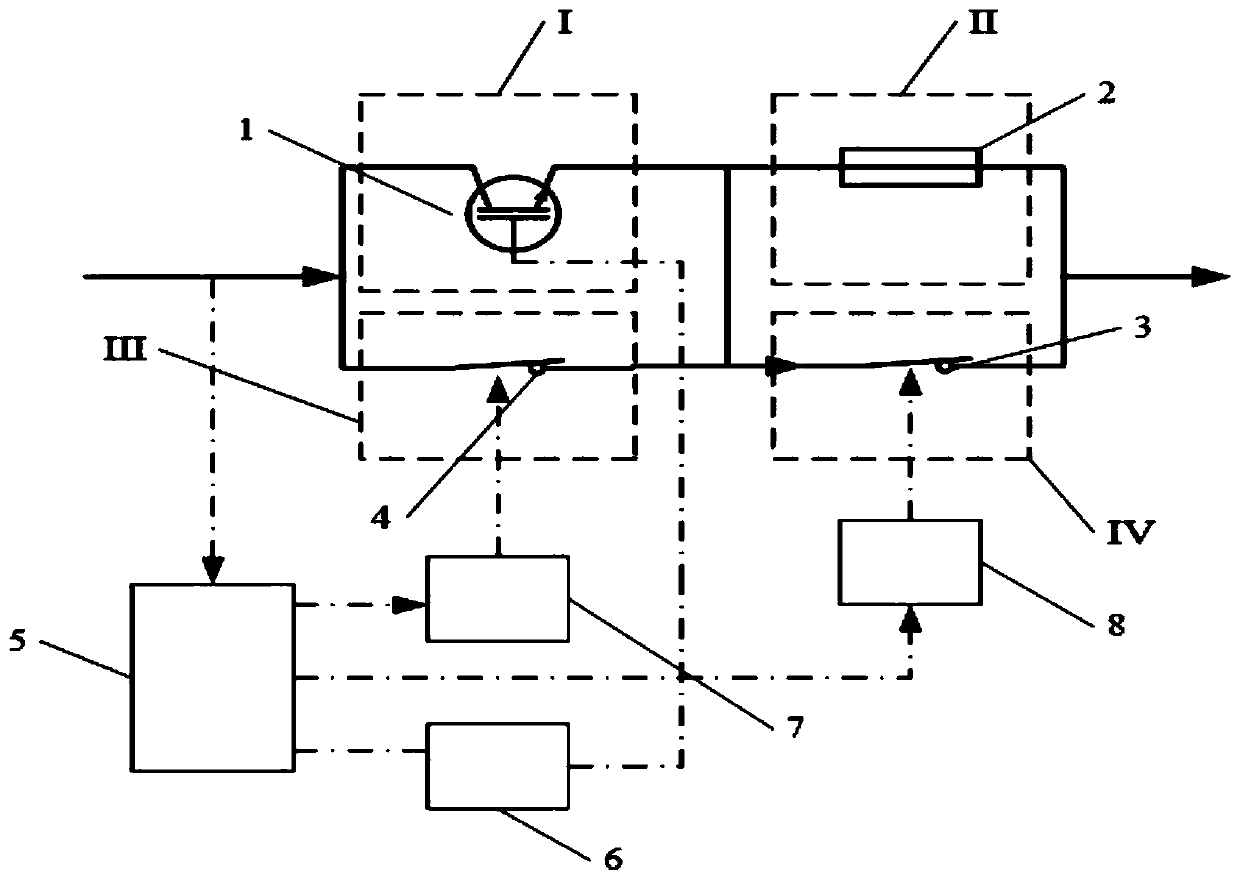
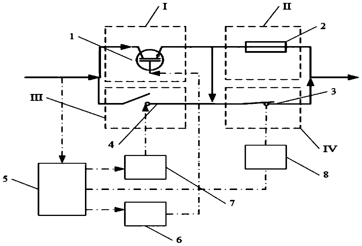
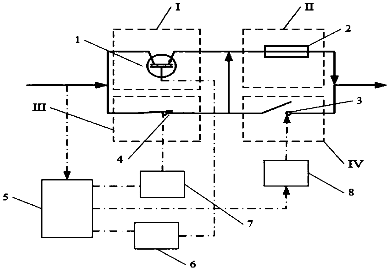
[0022] as attached figure 1 As shown, a DC electric vehicle power battery protection device according to the present invention includes four branches arranged on the main circuit of the electric vehicle power battery, and the first branch I and the third branch III of the four branches are connected in parallel , the second branch Ⅱ and the fourth branch Ⅳ are connected in parallel, and the two sets of parallel branches are connected in series again, and the two terminals formed, namely the incoming line end and the outgoing line end, are respectively connected to the circuit power supply and load on the main circuit of the electric vehicle power battery; The first branch I is composed of a power electronic switch 1; the second branch II is composed of a DC fuse 2; the third branch III and the fourth branch IV are respectively compose...


PUM


Abstract

The invention discloses a direct-current electric automobile power battery protection device and a work method thereof. The direct-current electric automobile power battery protection device includesfour branch circuits arranged on an electric automobile power battery main closed circuit, wherein the first branch circuit is alone composed of a power electronic switch, the second branch circuit isalone composed of a direct-current fuse protector, the third branch circuit and the fourth branch circuit are each alone composed of a direct-current mechanical switch, and the first and third branchcircuits are connected in parallel and then are in series connection with the second and fourth branch circuits which are connected in parallel; a control closed circuit of the device is provided with a current detection and control module for detecting the current state of the main closed circuit and controlling all the switches to be switched on and switched off so that different switch-on andswitch-off logic can be achieved. By adopting the device, the main closed circuit load current is on and off flows through the direct-current mechanical switches, the main closed circuit rated load current and overload current is off through when the power electronic switch, and the main closed circuit short-circuit current is off through the direct-current fuse protector; the switch-on and switch-off advantages of all the switches within different fault current ranges are fully exerted, direct-current electric automobile fault current is reliably broken, and therefore the device can replace current protection strategies.

Description

technical field [0001] The invention relates to the technical field of DC switching appliances, in particular to a DC electric vehicle power battery protection device and a working method thereof. Background technique [0002] At present, low-voltage direct current is more and more widely used, such as electric vehicles, which will gradually replace traditional fuel vehicles in the future and become one of the main means of transportation. Take electric vehicles as an example. In electric vehicles, the power battery is its core component. At present, the protection of the power battery adopts the method of connecting an air switch and a fuse in series. Among them, the air switch is responsible for breaking the rated current and small overload current, while the fuse is responsible for breaking the larger overload current and short-circuit current. However, in the actual use process, it is found that the fuses on the market can often effectively break 5 The current above 5 t...

Claims


Application Information

Patent Timeline
Patent Type & Authority Applications(China)
IPC IPC(8): B60L3/00B60L3/04
Inventor 刘志远高磊黄鑫健刘衍彬王建华耿英三项彬
Owner XI AN JIAOTONG UNIV
Learn More