Space-limited viscous damping wall

A viscous damping wall and space technology, applied in the field of viscous damping walls, to achieve the best design effect

Active Publication Date: 2019-05-21
深圳市美路科技有限公司
View PDF6 Cites 5 Cited by
  • Summary
  • Abstract
  • Description
  • Claims
  • Application Information

AI Technical Summary

Problems solved by technology

[0004] The purpose of the present invention is to provide a viscous damping wall with limited space to solve the problem of how to use the viscous damping wall to dissipate energy under the condition of limited space.

Method used


Image

  • Space-limited viscous damping wall
  • Space-limited viscous damping wall
  • Space-limited viscous damping wall

Examples


Embodiment 1

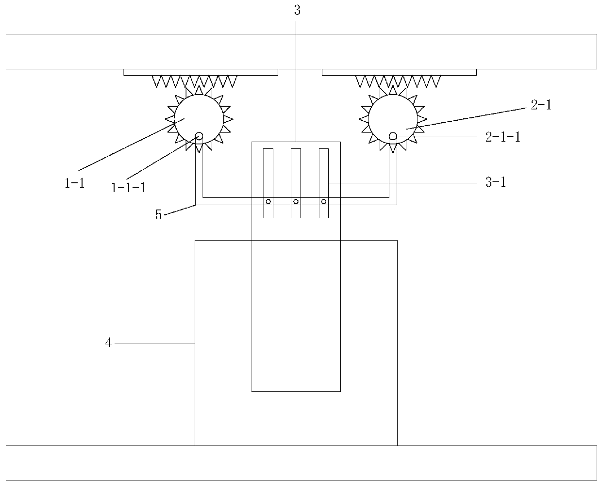
[0036] Embodiment 1, between the upper structure and the lower structure (the upper structure and the lower structure can be the upper beam and the lower beam), when the distance between the columns on both sides is small, or because the structural design only smaller spaces (such as Figure 4 shown) to install the viscous damping wall, according to the traditional design, the length of the viscous damping wall is too short. For this reason, propose the solution of this application:

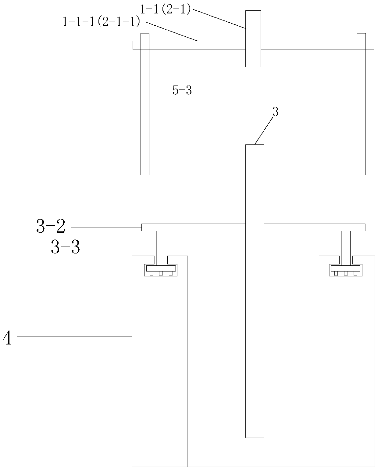
[0037] A viscous damping wall with limited space, comprising: a rack, a first gear assembly 1-1, a second gear assembly 2-1, a connecting frame 5, a middle plate 3, and an outer plate 4, and the middle plate 3 is arranged on Viscous liquid is filled between the outer plates 4 and between the middle plate 3 and the outer plates 4;

[0038] The rack is adapted to the first gear assembly 1-1 and the second gear assembly 2-1;

[0039] The structure of the first gear assembly 1-1 is the same as tha...

Embodiment 2

[0057] Embodiment 2, the number of meshing gears of the first gear assembly 1-1 and the second gear assembly 2-1 of the embodiment 1 is 1; the first gear assembly 1-1 of the embodiment 2, the second gear assembly 2 -1 contains 2 meshing gears;

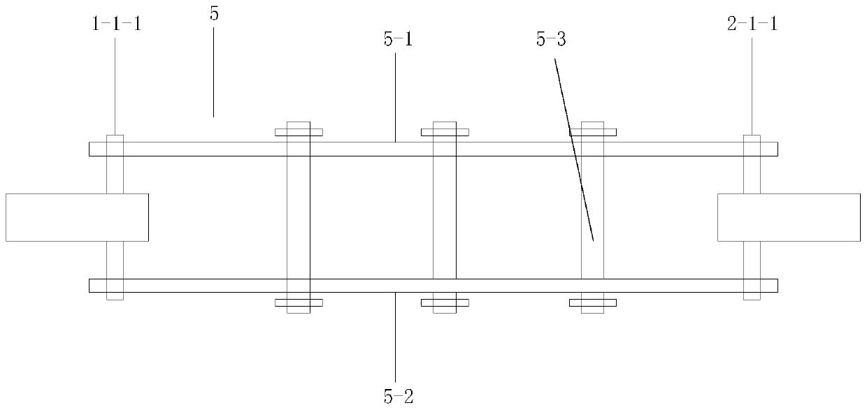
[0058] The first gear assembly 1-1 includes: 2 coaxial meshing gears, and a coaxial connection plate is arranged on the outside of the 2 meshing gears, and a coaxial connection plate is arranged on the outside of the connection plate and is perpendicular to the connection plate. The first connecting rod 5-1, the radius of the connecting plate on both sides of the first gear assembly 1-1 is larger than the radius of the gear;

[0059] The second gear assembly 2-1 has the same structure as the first gear assembly 1-1, including: 2 coaxial meshing gears, and a coaxial connecting plate is arranged on the outside of the 2 meshing gears. A second connecting rod 5-2 perpendicular to the connecting plate is arranged on the outer side of the c...


PUM


Abstract

The invention discloses a space-limited viscous damping wall which comprises a rack, a first gear assembly, a second gear assembly, a connecting frame, a middle plate and two outer side plates, the middle plate ise arranged between the outer side plates, and viscous liquid is packed between the outer side plates. Horizontal plates are vertically arranged on two sides of the middle plate, and rolling wheels are arranged on the lower sides of the horizontal plates. A groove is formed in the top end of each outer side plate, and the rolling wheels are matched with the grooves. The distance between a first rotating rod and the center of the first gear assembly is r, and the length of the strip-shaped groove exceeds 2r. The distance between the ends, in the beam length direction, of the outer side plates is larger than the sum of the length of an inner plate in the beam length direction and 2r. The rack is installed at the lower end of an upper beam, and the outer side plates, the first gear assembly and the second gear assembly are fixed to a lower beam. The invention aims to provide the space-limited viscous damping wall so as to solve the problem of how to install and design the viscous damping wall when the space is limited.

Description

technical field [0001] The invention relates to the fields of buildings, walls, disaster prevention and mitigation, and in particular to a viscous damping wall with limited space. Background technique [0002] In recent years, the research on the viscous damping wall has been greatly developed, such as: CN 108442565A provides a viscous damping wall, including an outer cavity, an inner cavity, a shearing device, a sealing device, a viscous liquid, a connecting device, Top plate and fixtures. The viscous liquid and the shearing device are arranged in the inner cavity, the inner cavity is arranged in the outer cavity, and the inner cavity can move laterally along the shearing device, and the sealing device is arranged between the shearing device and the inner cavity to ensure that the inner cavity Form a closed cavity. The connecting device is respectively connected with the top plate and the inner cavity, and the fixing device is respectively connected with the top plate and...

Claims


Application Information

Patent Timeline
Patent Type & Authority Applications(China)
IPC IPC(8): E04C2/00E04H9/02E04B1/98
Inventor 王翠丽
Owner 深圳市美路科技有限公司
Why Eureka
Try Eureka