Eureka AIR delivers breakthrough ideas for toughest innovation challenges, trusted by R&D personnel around the world.

Idler wheel rocking arm

A technology of rollers and rocker arms, applied in the direction of engine components, machines/engines, mechanical equipment, etc., can solve the problems of increased production costs, complex manufacturing processes, high requirements for component processing and assembly, and achieve simplified manufacturing processes and reduced components. The effect of processing

Pending Publication Date: 2019-05-21
HANGZHOU XZB TECH
View PDF0 Cites 0 Cited by
  • Summary
  • Abstract
  • Description
  • Claims
  • Application Information

AI Technical Summary

Problems solved by technology

[0003] In order to ensure that the needle roller and the outer ring of the roller will not have large axial displacement and deflection in the rocker frame, the existing roller rocker arm has high requirements for the size of each component, and the requirements for component processing and assembly are high. , the manufacturing process is complicated, which increases the production cost

Method used


Image

  • Idler wheel rocking arm
  • Idler wheel rocking arm
  • Idler wheel rocking arm

Examples


Embodiment 1

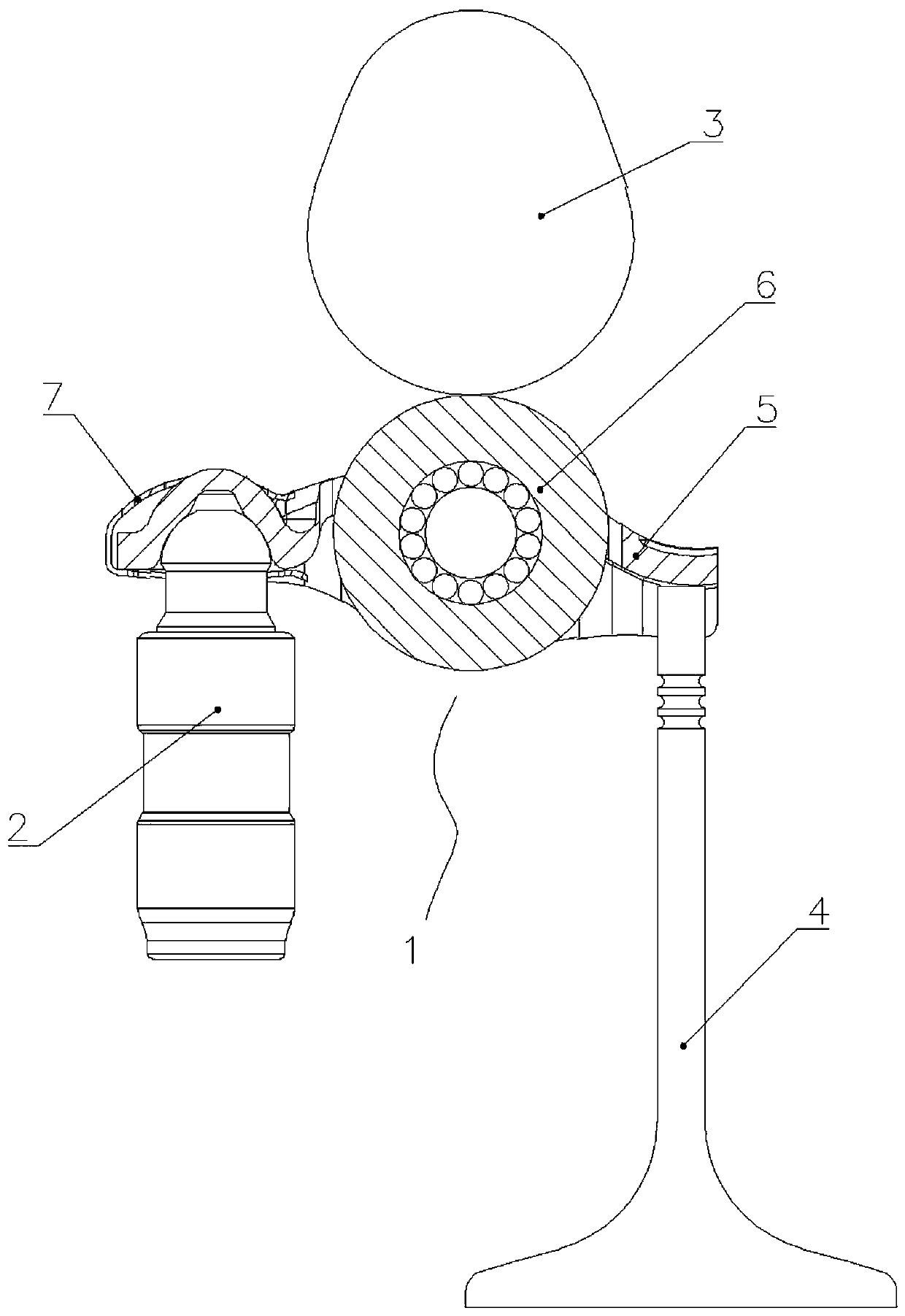
[0048] Embodiment one: if Figure 1-6 As shown, the roller rocker arm, the rocker arm mechanism 1 is installed between the tappet 2, the cam 3 and the valve 4, including the rocker arm frame 5 and the roller kit 6, the rocker arm frame 5 includes side walls 5.1, 5.2 and has a bearing surface 5.5, the bottom plate of the ball socket 5.6, there is an assembly hole 5.7 between the bearing surface 5.5 and the ball socket 5.6, pin holes 5.3, 5.4 are opened on the side walls 5.1, 5.2 located at the assembly hole 5.7, and the roller set 6 includes a pin shaft 6.1 , the roller outer ring 6.2 and the needle roller 6.3, the ball head of the tappet 2 is connected with the ball socket 5.6 through the ball card 7, the valve 4 slides against the bearing surface 5.5, and the roller assembly 6 is assembled in the pin hole 5.3 through the pin shaft 6.1, The assembly hole 5.7 between 5.4, the cam 3 rolls against the roller outer ring 6.2, through the rocker arm mechanism 1, the cam 3 transmits ...

Embodiment 2

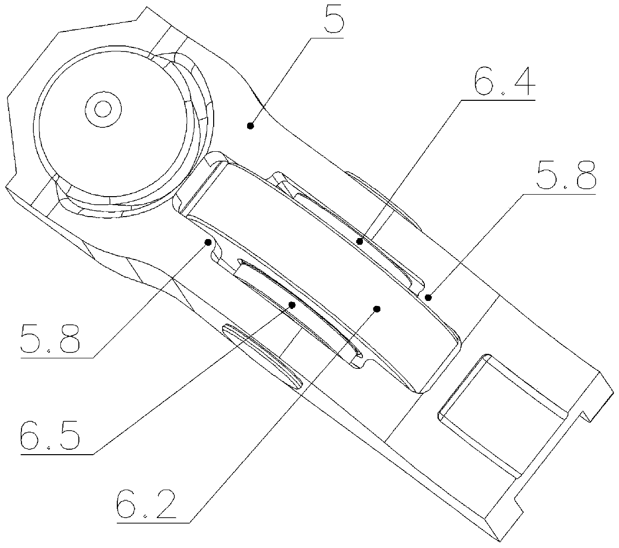
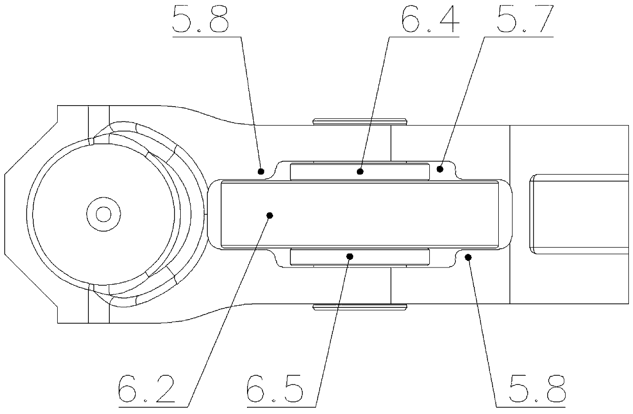
[0050] Embodiment 2: Combination Figure 7-11 As shown, the difference from Embodiment 1 is that the length of the needle roller 6.3 is greater than the width of the roller outer ring 6.2, and the retaining rings 6.4 and 6.5 are set on the needle roller 6.3. This embodiment does not need the step 5.8 structure, and the assembly hole 5.7 is integrated Square holes with the same width, retaining rings 6.4, 6.5 limit the axial movement of the roller outer ring 6.2, and the axial movement of the needle roller 6.3 is limited by the side walls 5.1, 5.2.

Embodiment 3

[0051] Example Three: Combining Figure 12-16 As shown, the difference from Embodiment 1 is that the retaining rings 6.4, 6.5 are set on the pin shaft 6.1, the length of the needle roller 6.3 is not greater than the width of the roller outer ring 6.2, and the outer diameter of the retaining rings 6.4, 6.5 is larger than the roller outer ring 6.2 In this embodiment, the step 5.8 structure is not required, the assembly hole 5.7 is a square hole with the same overall width, and the retaining rings 6.4 and 6.5 simultaneously limit the axial movement of the roller outer ring 6.2 and the needle roller 6.3.


PUM


Abstract

The invention provides an idler wheel rocking arm. A rocking arm mechanism is mounted among a tappet, a cam and an air valve, and comprises a rocking arm frame and an idler wheel sleeve piece; the rocking arm frame comprises side walls and a bottom plate with a bearing face and a ball socket, an assembly hole is formed between the bearing face and the ball socket, and pin shaft holes are formed inthe positions, at the assembly hole, on the side walls; the idler wheel sleeve piece comprises a pin shaft, an idler wheel outer ring and a roller pin; a ball head of the tappet is connected with theball socket through a ball head clamping piece, and the air valve and the bearing face slidably abut against each other; the idler wheel sleeve piece is assembled into the assembly hole between the pin shaft holes through the pin shaft, and the cam and the idler wheel outer ring abut against each other in a rolling mode; and check rings are arranged at the two ends of the idler wheel sleeve pieces in a sleeving mode, and the check rings limit axial displacement of the idler wheel outer ring and or / and the roller pin. According to the idler wheel rocking arm, the problems of axial displacementand inclination of the idler wheel sleeve piece are effectively solved, a manufacturing process is simplified, and the requirements of part machining and assembly and the production cost are lowered.

Description

technical field [0001] The invention relates to the technical field of engine accessories, in particular to a roller rocker arm. Background technique [0002] The roller rocker arm is installed between the tappet, the cam and the valve. It is an important part used in the engine power system. It is composed of a rocker arm frame, a pin shaft, a needle roller, and a roller outer ring. [0003] In order to ensure that the needle roller and the outer ring of the roller will not have large axial displacement and deflection in the rocker frame, the existing roller rocker arm has high requirements for the size of each component, and the requirements for component processing and assembly are high. , the manufacturing process is complicated, which increases the production cost. Contents of the invention [0004] The present invention aims to solve the problems of the prior art, and provides a roller rocker arm, which has a simple manufacturing process and reduces the requirements...

Claims


Application Information

Patent Timeline
Patent Type & Authority Applications(China)
IPC IPC(8): F01L1/18
Inventor 徐纳任海军
Owner HANGZHOU XZB TECH
Why Eureka
Eureka Blog
Learn More