Waste gas emission system for dual-fuel engine

A technology of exhaust gas emission system and dual-fuel engine, applied in the direction of engine components, machines/engines, exhaust devices, etc., capable of solving problems such as explosion, engine component damage, and damage to the exhaust system

Active Publication Date: 2019-05-21
PAXOCEAN ENG ZHOUSHAN CO LTD
View PDF5 Cites 3 Cited by
  • Summary
  • Abstract
  • Description
  • Claims
  • Application Information

AI Technical Summary

Problems solved by technology

[0002] When a dual-fuel engine (natural gas-diesel dual-fuel engine) fails during natural gas mode operation, natural gas may enter the exhaust system, making it possible for natural gas to accumulate on the exhaust pipe. Once the natural gas in the exhaust pipe encounters a fire If the source is ignited, it will explode, damage the exhaust system, and even cause damage to engine components.

Method used


Image

  • Waste gas emission system for dual-fuel engine
  • Waste gas emission system for dual-fuel engine
  • Waste gas emission system for dual-fuel engine

Examples


specific Embodiment 1

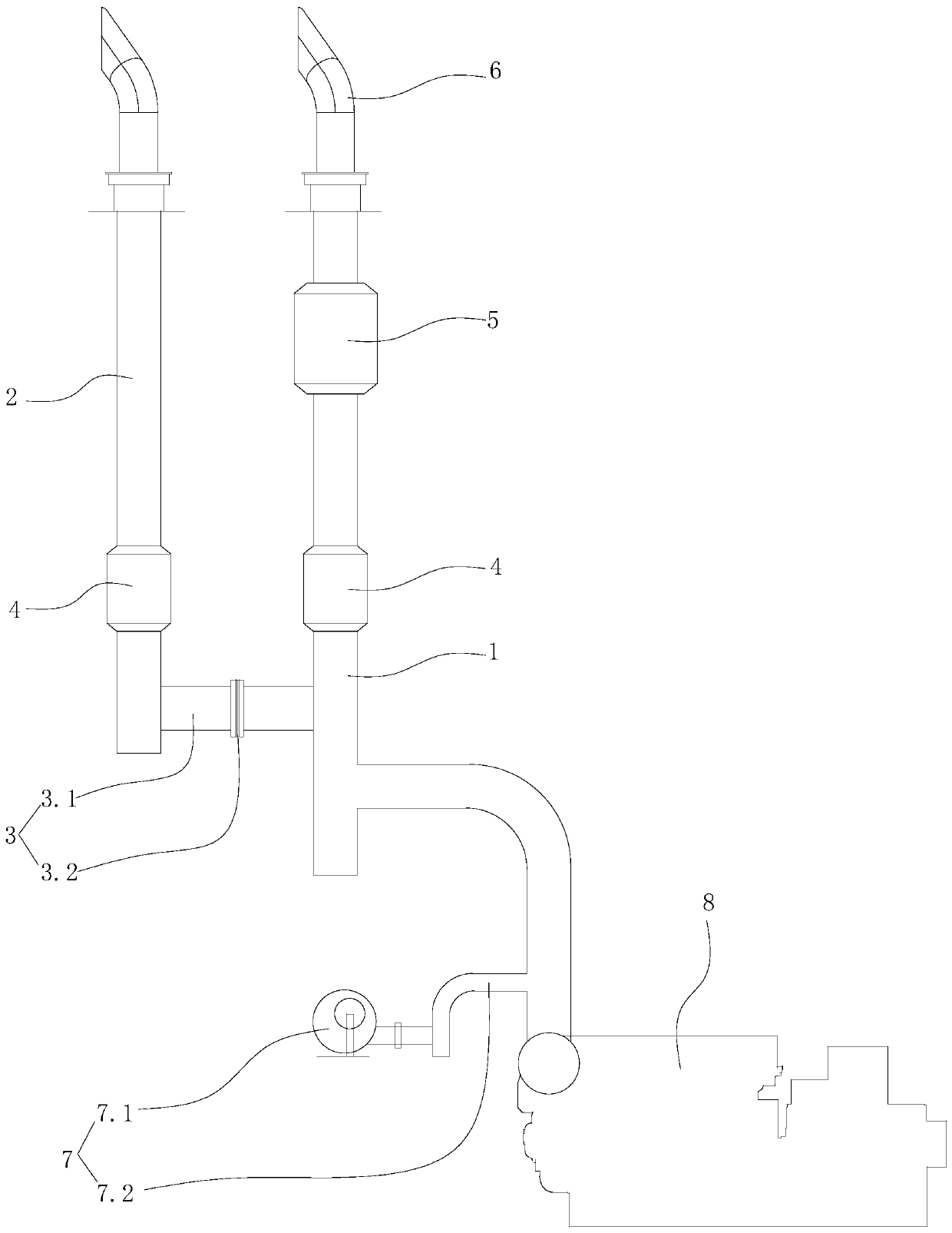
[0039] Specific embodiment one: such as figure 1 As shown, an exhaust gas exhaust system for a dual-fuel engine includes a main exhaust line, a backup exhaust line, and an explosion-proof connection device 3. The main exhaust line is used to discharge exhaust gas discharged from the operation of the engine, and the main exhaust line includes a main exhaust pipe 1 connected to the exhaust gas discharge port of the engine 8. The spare exhaust pipe includes a spare exhaust pipe 2, one end of the spare exhaust pipe is closed, and the other end of the spare exhaust pipe forms a spare exhaust port. The explosion-proof connecting device 3 includes an explosion-proof connecting pipe 3.1 connecting the main exhaust pipe and the backup exhaust pipe, and an explosion-proof protective sheet 3.2 for isolating the explosion-proof connecting pipe. The explosion-proof protective sheet cuts off the explosion-proof connecting pipe so that the main exhaust pipe and the spare exhaust pipe Trachea ...

specific Embodiment 2

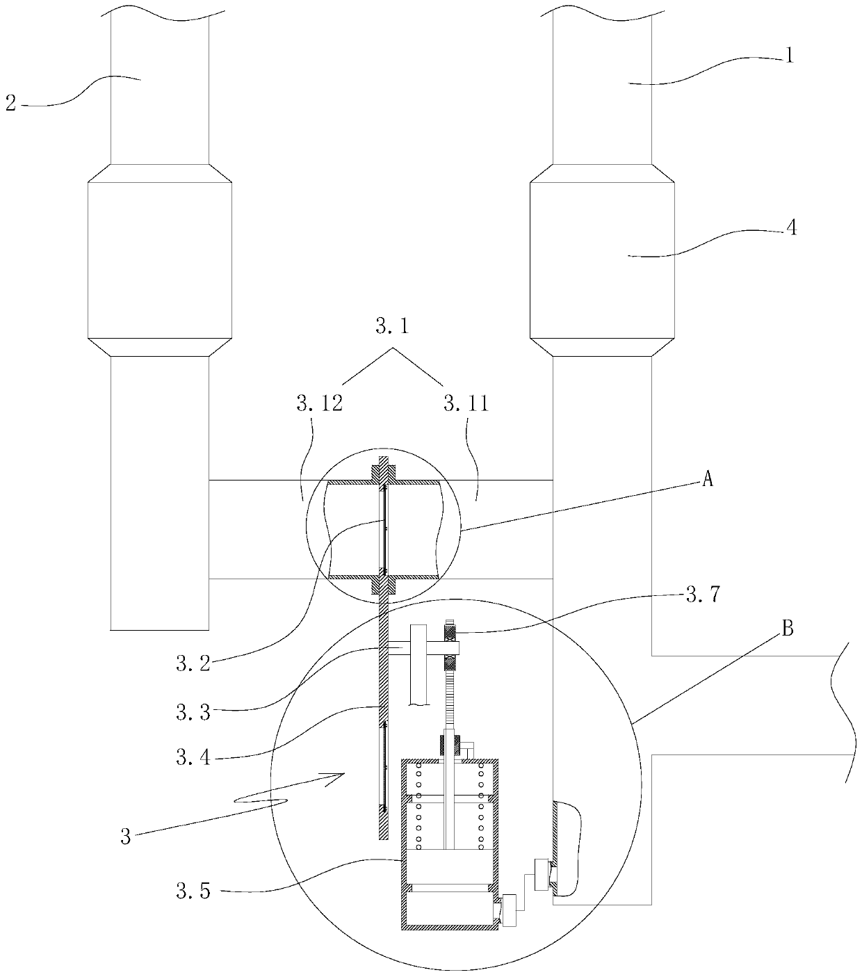
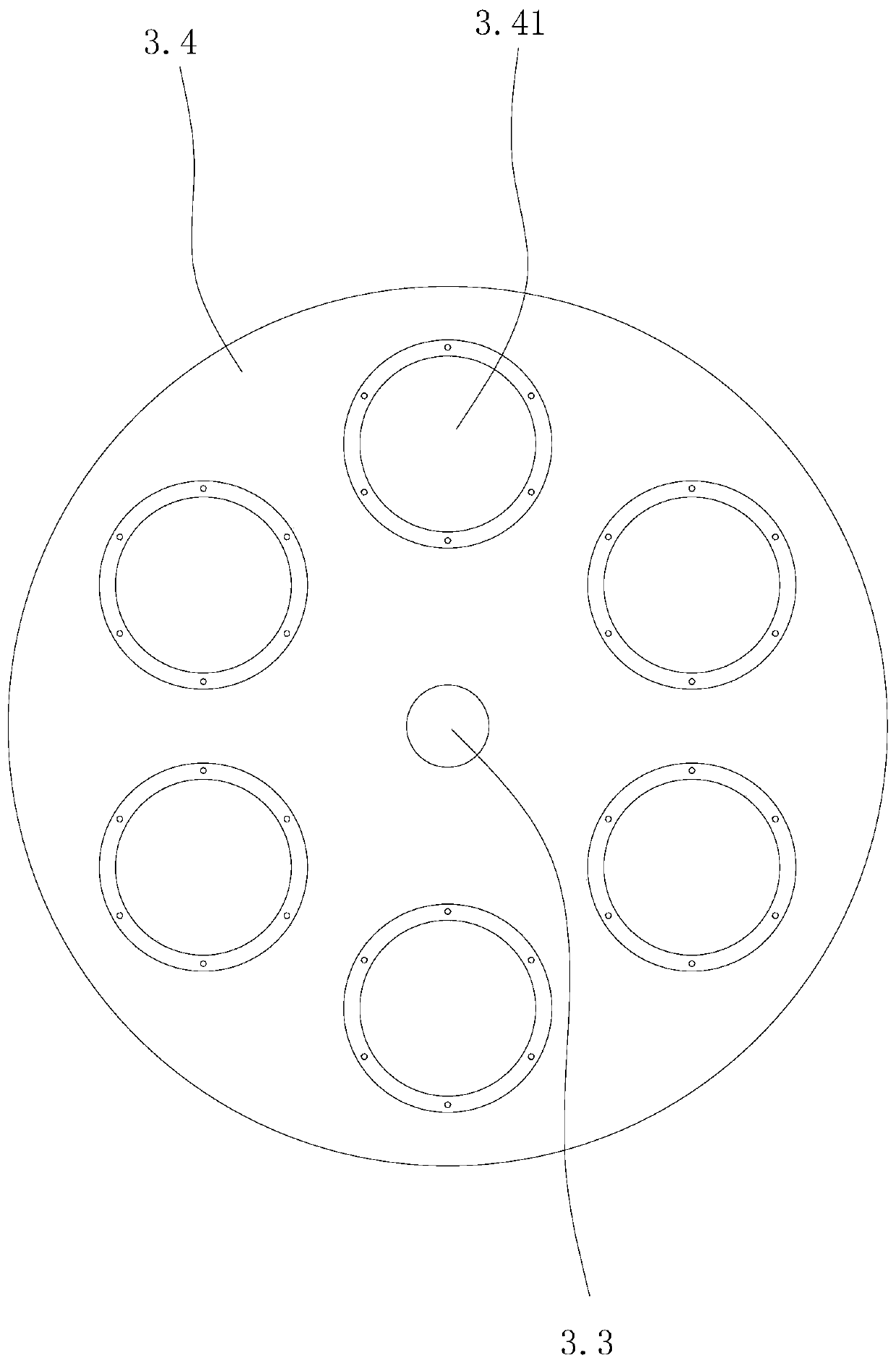
[0046] Specific embodiment 2: For the specific structure of this embodiment, refer to specific embodiment 1. The difference lies in: figure 2 , image 3 , Figure 4 , Figure 5 As shown, the explosion-proof connection device also includes a main shaft rod 3.3 arranged on the hull through a bearing rotation, an explosion-proof protection plate mounting plate 3.4 coaxially arranged on the main shaft rod, and N pieces of the explosion-proof protection plate installation plate evenly distributed around the shaft rod in the circumferential direction Explosion-proof protection plate mounting hole 3.41, drive gear 3.7 arranged on the spindle rod through a one-way bearing 3.6, rack gear 3.8 meshed with the drive gear, switching cylinder 3.5 arranged on the hull, arranged in the switching cylinder The first limiting block 3.51 and the second limiting block 3.52 on the side surface are slidably arranged in the switching cylinder and located between the first limiting block and the second...


PUM


Abstract

The invention discloses a waste gas emission system for a dual-fuel engine and aims at providing the waste gas emission system for the dual-fuel engine, capable of effectively preventing that naturalgas in an exhaust pipeline is ignited and exploded to destroy an exhaust system, and even cause damages of an engine part and the like. The waste gas emission system for the dual-fuel engine comprisesa main exhaust pipeline, a standby exhaust pipeline and an anti-explosion connecting device; the main exhaust pipeline comprises a main exhaust pipe connected with an engine; the standby exhaust pipeline comprises a standby exhaust pipe; the anti-explosion connecting device comprises an anti-explosion connecting piece which is connected with the main exhaust pipe and the standby exhaust pipe andan anti-explosion protective piece used for partitioning the anti-explosion connecting pipe; the anti-explosion protective piece partitions the anti-explosion connecting pipe to enable the main exhaust pipe to be isolated from the standby exhaust pipe; and when the pressure intensity in the main exhaust pipe is larger than a set value P1, the anti-explosion protective piece is broken, so that gasin the main exhaust pipe can enter the standby exhaust pipe through a connecting pipeline.

Description

Technical field [0001] The invention relates to an exhaust gas emission system of an engine, in particular to an exhaust gas emission system for a dual-fuel engine. Background technique [0002] When a dual-fuel engine (natural gas-diesel dual-fuel engine) fails during the natural gas mode operation, natural gas can enter the exhaust system, so that natural gas may accumulate on the exhaust pipe. Once the natural gas in the exhaust pipe encounters a fire The source will be ignited and explode, destroying the exhaust system, and even causing damage to engine components. In view of this, how to design a dual-fuel engine exhaust emission system to solve the above problems is very important. Summary of the invention [0003] The purpose of the present invention is to overcome the deficiencies in the prior art, and provide a dual-use system that can effectively prevent the natural gas in the exhaust pipeline from igniting and exploding, which will damage the exhaust system and even ca...

Claims


Application Information

Patent Timeline
Patent Type & Authority Applications(China)
IPC IPC(8): F01N13/08
Inventor 刘祯姜峰欧旭斌冯文刚董国付
Owner PAXOCEAN ENG ZHOUSHAN CO LTD
Why Eureka
Try Eureka