Supercharge Your Innovation With Domain-Expert AI Agents!

Heat pipeline paving equipment

A technology for thermal pipelines and equipment, applied in the field of thermal pipeline laying equipment, can solve problems such as inconvenient inspection, increased workload, secondary excavation, etc., and achieve the effects of easy inspection, small workload, and good thermal insulation performance

Active Publication Date: 2019-05-21
北京城建二建设工程有限公司
View PDF5 Cites 1 Cited by
  • Summary
  • Abstract
  • Description
  • Claims
  • Application Information

AI Technical Summary

Problems solved by technology

[0005] In view of this, the present invention provides a heat pipe laying equipment, which can solve the problem that during the heat pipe laying process, personnel usually bury the heat pipe in the soil, the heat preservation effect is general, and secondary excavation is required for later maintenance, which increases the workload. , and inspection inconvenience and other problems

Method used


Image

  • Heat pipeline paving equipment
  • Heat pipeline paving equipment
  • Heat pipeline paving equipment

Examples


Embodiment Construction

[0030] Embodiments of the present invention will be described below with reference to the drawings. In the process, in order to ensure the clarity and convenience of illustration, we may exaggerate the width of the lines or the size of the constituent elements in the diagram.

[0031] In addition, the following terms are defined based on the functions in the present invention, and may be different according to the user's or operator's intention or practice. Therefore, these terms are defined based on the entire content of this specification.

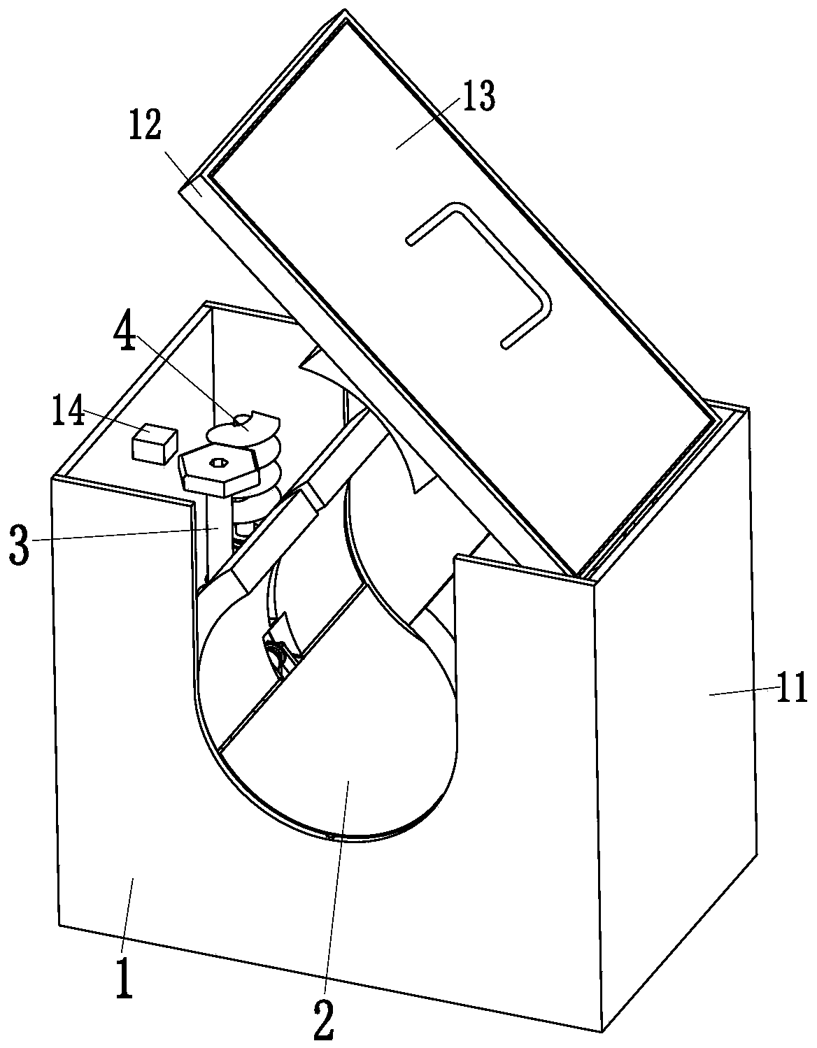
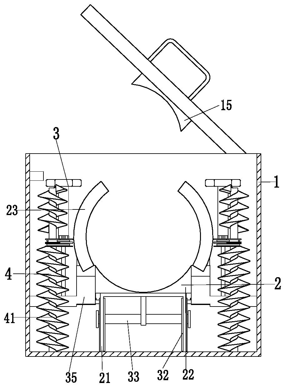
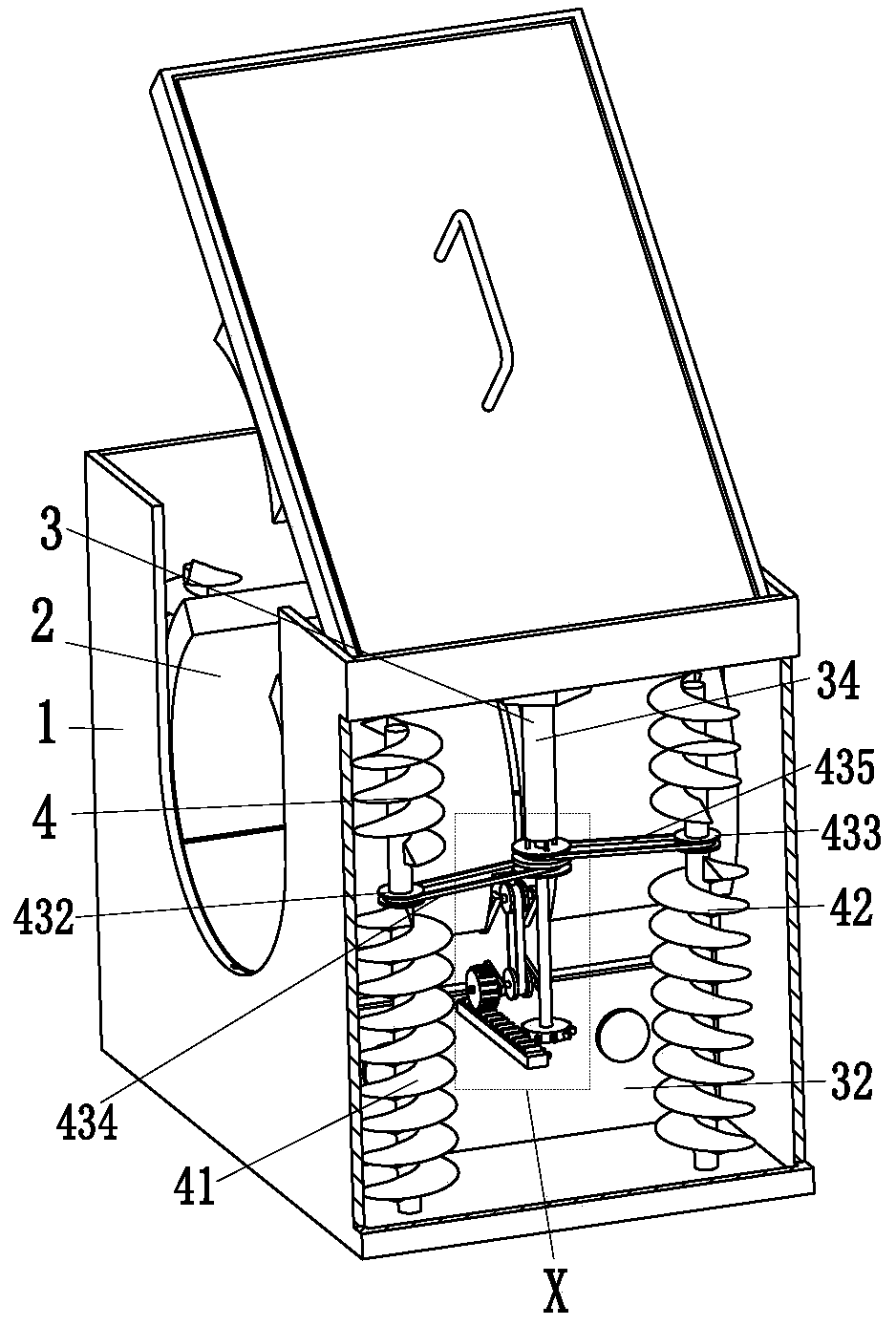
[0032] Such as Figure 1 to Figure 5 As shown, a thermal pipeline laying equipment includes a main frame 1, a thermal insulation frame 2, two adjustment devices 3 and two crushing devices 4, the bottom middle of the main frame 1 is equipped with a thermal insulation frame 2, and the thermal insulation frame Two adjustment devices 3 are connected to the left and right ends of 2, and the two adjustment devices 3 are installed on the main...


PUM


Abstract

The invention relates to heat pipeline paving equipment. The heat pipeline paving equipment comprises a main frame, a thermal insulation frame, two regulating devices and two smashing devices, whereinthe middle part of the bottom end of the main frame is equipped with the thermal insulation frame; left and right ends of the thermal insulation frame are connected with the two regulating devices; the two regulating devices are mounted on the main frame; and left and right sides of the bottom end of the main frame are equipped with the two smashing devices. The heat pipeline paving equipment cansolve the problems that thermal insulation effect is common as staff generally embeds a heat pipeline into soil in a heat pipeline paving process, workload is increased as secondary excavation is needed during later-stage maintenance, checking is inconvenient, and the like, and has the advantages that thermal insulation is good, checking can be performed by only needing to clear the soil at the upper end during later-stage maintenance, checking is easy, workload is small, crush resistance is achieved, and the like.

Description

technical field [0001] The invention relates to the field of heat pipe laying, in particular to a heat pipe laying equipment. Background technique [0002] In recent years, with the increase in demand for heating, the distance and diameter of thermal pipelines installed in pipe galleries and tunnels has continued to increase, and the safety and stability of the pipeline network have received more and more attention. Also known as heat pipe network, it starts from the boiler room, direct-fired machine room, heating center, etc., and leads from the heat source to the heat supply pipe of the building's heat entrance. [0003] Usually, thermal pipes are usually buried directly in trenches. However, thermal pipes directly buried in the soil often have the following problems: 1. The insulation effect is average; Re-excavation is required, which increases the workload and makes inspection inconvenient. [0004] There are also some technical solutions for thermal pipelines in the ...

Claims


Application Information

Patent Timeline
Patent Type & Authority Applications(China)
IPC IPC(8): F16L1/028F16L1/06F16L59/02B02C18/08B02C18/18B02C18/24
Inventor 沙雨亭李金凤李曼焦浩韦小玲王志强王旭王浦春陈敬雨朱家业吴国珍何攀
Owner 北京城建二建设工程有限公司
Features
  • R&D
  • Intellectual Property
  • Life Sciences
  • Materials
  • Tech Scout
  • Unparalleled Data Quality
  • Higher Quality Content
  • 60% Fewer Hallucinations
Learn More