Thermal insulation structure of thermal medium storage tank and thermal medium pipe of solar photo-thermal power generation system

A technology of photothermal power generation and heat medium, applied in pipeline protection, pipeline protection through heat insulation, heat preservation, etc., can solve problems such as difficulties in manufacturing, operation and maintenance, and achieve good heat insulation effects

Active Publication Date: 2013-08-07
常州循天节能科技有限公司
View PDF10 Cites 10 Cited by
  • Summary
  • Abstract
  • Description
  • Claims
  • Application Information

AI Technical Summary

Problems solved by technology

However, this vacuum system has many difficulties in manufacturing, operation and maintenance.

Method used


Image

  • Thermal insulation structure of thermal medium storage tank and thermal medium pipe of solar photo-thermal power generation system
  • Thermal insulation structure of thermal medium storage tank and thermal medium pipe of solar photo-thermal power generation system
  • Thermal insulation structure of thermal medium storage tank and thermal medium pipe of solar photo-thermal power generation system

Examples


Embodiment 1

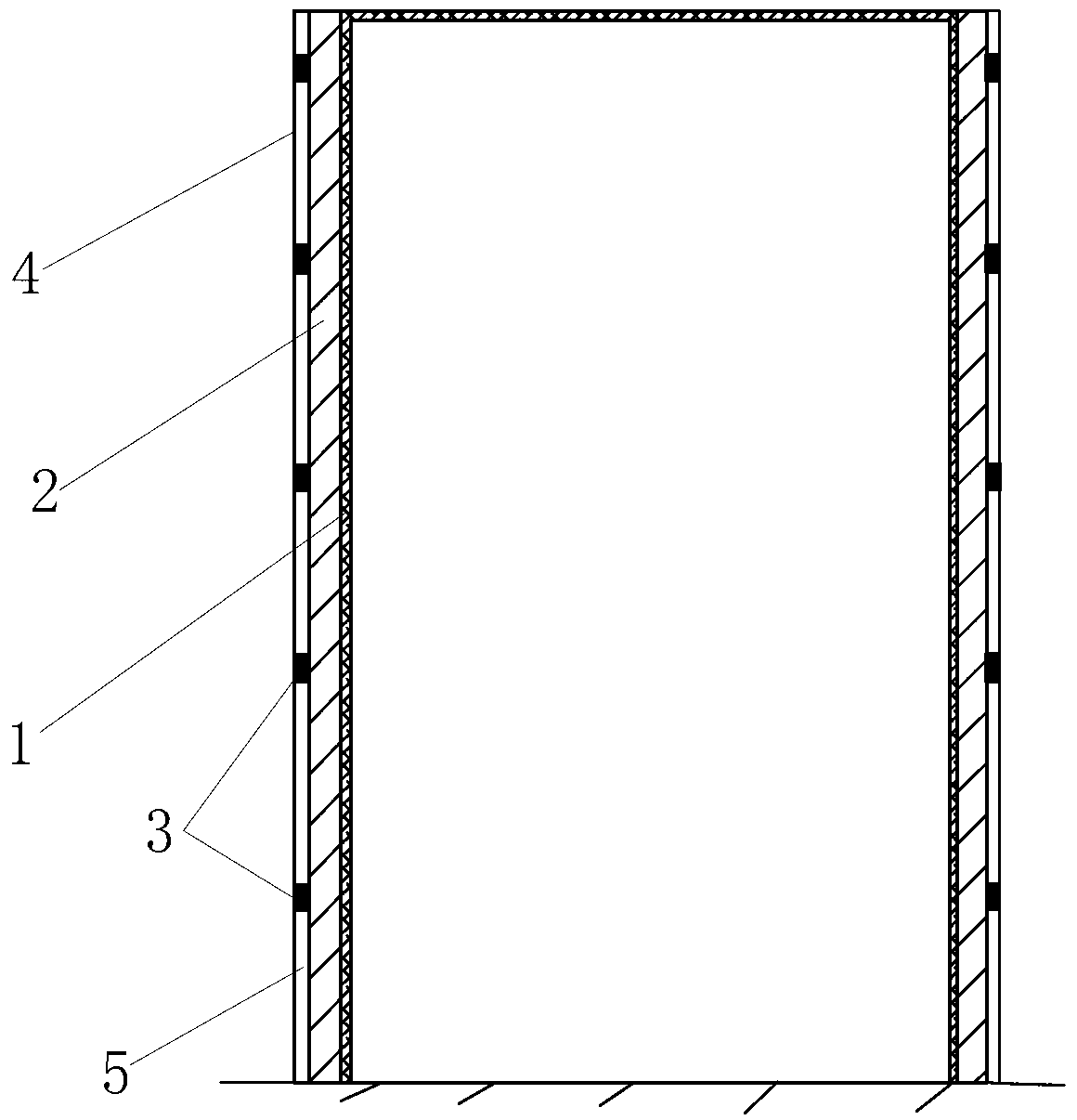
[0042] (Example 1, thermal insulation structure of heat medium storage tank)

[0043] See figure 1 , The thermal insulation structure of the heat medium storage tank of the solar thermal power generation system in this embodiment includes a thermal insulation composite layer 2 , a fixing piece, a support bar 3 and an outer protective layer 4 . Fixing parts are galvanized iron wire. The heat medium in the heat medium storage tank is molten salt or heat transfer oil. There are 4 to 6 groups of thermal insulation composite layers 2, and each group of thermal insulation composite layers 2 is wrapped group by group on the outer peripheral surface of the tank body 1 of the heat medium storage tank in sequence from the inside to the outside, and is bound group by group by the iron wire of the fixing part fixed on the tank body 1. That is, the first group of thermal insulation composite layers 2 is wrapped around the tank body 1 and fixed by iron wires; the second group of thermal ...

Embodiment 2

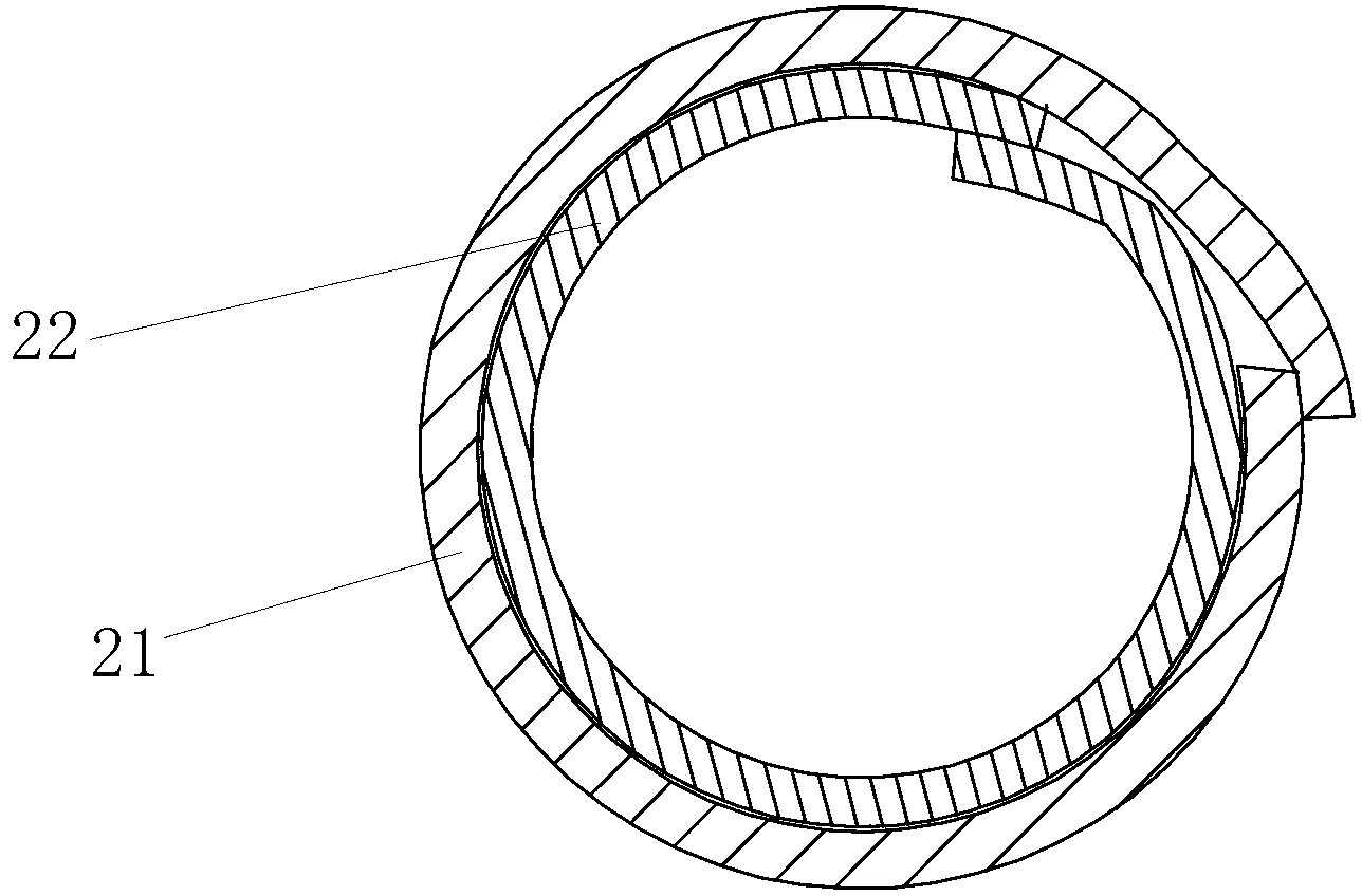
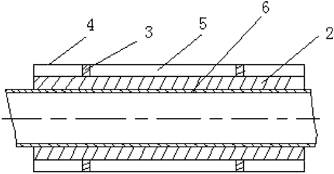
[0065] (Example 2, insulation structure of heat medium pipeline)

[0066] The thermal insulation structure of the heat medium pipeline of the solar thermal power generation system in this embodiment includes a thermal insulation composite layer 2 , a fixing piece, a support bar 3 and an outer protective layer 4 . Fixing parts are galvanized iron wire. There are 1 to 6 groups of thermal insulation composite layers 2, and each group of thermal insulation composite layers 2 is wrapped on the outer peripheral surface of the pipeline 6 group by group according to the order from the inside to the outside, and is fixed on the pipeline 6 group by group by fixing iron wires. That is, the first group of thermal insulation composite layers 2 is wrapped on the pipe 6 and fixed by iron wires; the second group of thermal insulation composite layers 2 is wrapped on the first group of thermal insulation composite layers 2 and fixed by iron wires; and so on until the final The outer 1 group o...

Embodiment 3

[0073] (Example 3, insulation structure of heat medium pipeline)

[0074] The rest of the thermal insulation structure of the heat medium pipeline in this embodiment is the same as that in Embodiment 1, except that the pipeline 6 in this embodiment is a pipeline for transporting 300°C steam, and when the steam transportation pipeline 6 is insulated, it is laid sequentially from the inside to the outside 3 sets of thermal insulation composite layers 2.

[0075] The inner first group of thermal insulation composite layer 2 is made up of 3mm thick glass fiber felt and 6mm thick high temperature type airgel thermal insulation blanket. The second group of thermal insulation composite layer 2 consists of a 25mm thick aluminum silicate fiber blanket and a 6mm thick high temperature airgel thermal insulation blanket. The third group of thermal insulation composite layer 2 is composed of 3mm thick glass fiber felt and 6mm thick medium temperature airgel thermal insulation blanket.

...


PUM


Abstract

The invention discloses a thermal insulation structure of a thermal medium storage tank and a thermal medium pipe of a solar photo-thermal power generation system. The thermal insulation structure comprises thermal insulation composite layers, fixed parts, support strips and an outer protecting layer. All groups of thermal insulation composite layers are sequentially wrapped on a tank body of the thermal medium storage tank or the peripheral surface of the thermal medium pipe group by group according to a sequence from inside to outside. The support strips are fixed outside the thermal insulation composite layer of the outermost side in a surrounded mode along the circumference and are one layer or two layers of stacked aerogel strips of 1-3cm in thickness; and the support strips are parallelly arranged on the thermal insulation composite layer of the outermost side at intervals of 0.5-1.0 meter. The outer protecting layer is wrapped on the outer side of the support strips, and an annular cavity is formed between the outer protecting layer and the thermal insulation composite layer of the outermost side and is an air thermal insulation layer. According to the thermal insulation structure, a mode of jointly utilizing the thermal insulation composite layers and the air thermal insulation layer on the outer surface of the tank body or the pipe is adopted, thermal insulation effect is remarkable, and cost of the air thermal insulation layer is extremely low.

Description

technical field [0001] The invention relates to the field of thermal insulation, in particular to thermal medium storage tanks and pipeline thermal insulation structures of solar thermal power generation systems. Background technique [0002] Solar thermal power generation refers to the use of large-scale arrays of parabolic or dish-shaped mirrors to collect solar heat, provide steam through heat exchange devices, and combine traditional turbogenerator technology to achieve the purpose of power generation. [0003] The theoretical advantages of solar thermal power generation are: thermal energy accounts for more than 60% of solar energy, and solar thermal power generation directly outputs AC power. The cost of solar thermal power generation is lower than that of photovoltaic power generation with silicon cells, and solar thermal power generation is suitable for high-power development. The use of solar thermal power generation technology avoids the expensive silicon crystal p...

Claims


Application Information

Patent Timeline
Patent Type & Authority Applications(China)
IPC IPC(8): B65D81/38B65D90/06F16L59/02F16L59/08
CPCF28D20/00F28F2270/00Y02E60/14Y02E70/30
Inventor 徐俊伟敖文亮陈精明
Owner 常州循天节能科技有限公司
Why Eureka
Try Eureka