An ultrasonic wind speed and direction measurement experimental instrument and measurement method

A measurement method, wind speed and wind direction technology, applied in the direction of fluid velocity measurement, velocity/acceleration/shock measurement, measuring device, etc., can solve the problems of limited applicable occasions, short service life, and large influence of ambient temperature, so as to avoid mechanical The effect of exercise

Inactive Publication Date: 2021-02-19
UNIV OF JINAN
View PDF14 Cites 0 Cited by
  • Summary
  • Abstract
  • Description
  • Claims
  • Application Information

AI Technical Summary

Problems solved by technology

Wing-shaped anemometers and cup-shaped anemometers are easy to use, but their mechanical friction resistance and inertia are relatively large, and they are only suitable for measuring high wind speeds, and cannot be used for some occasions that need to measure small wind speeds; commonly used mechanical instruments Because there are many moving parts, there are disadvantages such as structural wear, short service life, inability to use in harsh environments, and high maintenance costs. In addition, limited by the mechanical structure and the measurement principle of mechanical wind measuring instruments, mechanical wind measuring instruments The sensitivity of the thermal anemometer is also low; due to the limitation of its own measurement principle, the thermal anemometer is greatly affected by the ambient temperature, so its applicable occasions are limited; and most of the existing ultrasonic anemometers are based on time difference and frequency difference. , phase difference or Doppler effect and other measurement methods, but the core of the above measurement methods is still based on absolute time (or time difference) measurement, so this type of method has a very high accuracy for time (difference) measurement circuits and related algorithms requirements, this is the deficiency of the prior art

Method used


Image

  • An ultrasonic wind speed and direction measurement experimental instrument and measurement method
  • An ultrasonic wind speed and direction measurement experimental instrument and measurement method
  • An ultrasonic wind speed and direction measurement experimental instrument and measurement method

Examples


Embodiment 1

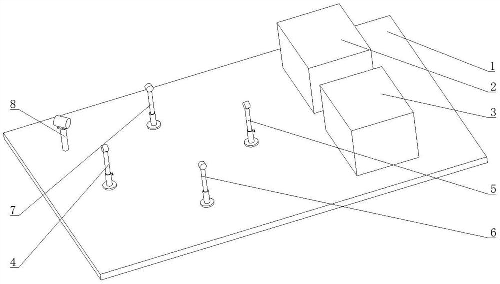
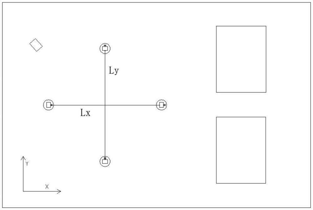
[0169] Experimental conditions:

[0170] wind direction first quadrant Ultrasonic frequency f 0 (KHz)

40.00 path lengthL x (m)

0.328 path lengthL y (m)

0.328

[0171] Experimental results:

[0172]

Embodiment 2

[0174] Experimental conditions:

[0175] wind direction second quadrant Ultrasonic frequency f 0 (KHz)

40.00 path lengthL x (m)

0.328 path lengthL y (m)

0.328

[0176] Experimental results:

[0177]

Embodiment 3

[0179] Experimental conditions:

[0180] wind direction third quadrant Ultrasonic frequency f 0 (KHz)

40.00 path lengthL x (m)

0.328 path lengthL y (m)

0.328

[0181] Experimental results:

[0182]


PUM


Abstract

The invention discloses an ultrasonic wind speed and wind direction measurement experimental instrument and a measurement method, which includes a base, and is characterized in that: the upper side of the base is fixedly connected with a function signal generator, an oscilloscope, an ultrasonic generator 1, an ultrasonic receiver 1, and an ultrasonic generator Two and ultrasonic receiver two, a fan is placed on the base, the first ultrasonic generator is facing the first ultrasonic receiver, and the second ultrasonic generator is facing the second ultrasonic receiver. The invention relates to the field of measuring equipment, in particular to an experimental instrument for measuring ultrasonic wind speed and direction. The advantage of the present invention is that compared with the original wind speed measurement method, this measurement method not only avoids the mechanical movement of the measurement device, but also does not depend on the accuracy of the time (difference) measurement circuit, so it is less affected by external factors in theory, And it is a non-contact measurement method.

Description

technical field [0001] The invention relates to the field of measuring equipment, in particular to an ultrasonic wind speed and direction measurement experiment instrument and a measurement method. Background technique [0002] In terms of wind speed and direction measurement, currently commonly used instruments include wing anemometer, cup anemometer, thermal anemometer and ultrasonic anemometer. Wing-shaped anemometers and cup-shaped anemometers are easy to use, but their mechanical friction resistance and inertia are relatively large, and they are only suitable for measuring high wind speeds, and cannot be used for some occasions that need to measure small wind speeds; commonly used mechanical instruments Because there are many moving parts, there are disadvantages such as structural wear, short service life, inability to use in harsh environments, and high maintenance costs. In addition, limited by the mechanical structure and the measurement principle of mechanical wind...

Claims


Application Information

Patent Timeline
Patent Type & Authority Patents(China)
IPC IPC(8): G01P5/24G01P13/02
Inventor 荣振宇张莉张宁
Owner UNIV OF JINAN
Why Eureka
Try Eureka