
A real-time detection device for power quality

A technology of real-time detection and power quality, applied in the direction of measuring devices, measuring device shells, measuring electrical variables, etc., can solve problems such as damage, easy aging of internal parts, unfavorable accuracy, etc., to avoid measurement errors, prolong service life, increase The effect of large accuracy

Active Publication Date: 2021-03-23
日照阳光电力设计有限公司 +1
View PDF12 Cites 0 Cited by
  • Summary
  • Abstract
  • Description
  • Claims
  • Application Information

AI Technical Summary

Problems solved by technology

[0003] The traditional power quality detection device is an integrated structure, which cannot be installed and disassembled by itself. The internal parts of the machine are easily aging after a long period of use. The integrated design makes the internal aging parts unable to be replaced, causing errors in the detection data, which is not conducive to the accuracy of the detection; the traditional power quality The detection device has no protective measures, and external impacts can easily cause the vibration of the power quality detection device to damage the internal parts, which greatly reduces the service life of the power quality detection device. In view of these defects, it is necessary to design a real-time detection device for power quality

Method used


Image

  • A real-time detection device for power quality
  • A real-time detection device for power quality
  • A real-time detection device for power quality

Examples


Embodiment Construction

[0018] The present invention will be further described below in combination with specific embodiments. Wherein, the accompanying drawings are only for illustrative purposes, showing only schematic diagrams, rather than physical drawings, and should not be construed as limitations on this patent; in order to better illustrate the embodiments of the present invention, some parts of the accompanying drawings will be omitted, Enlargement or reduction does not represent the size of the actual product; for those skilled in the art, it is understandable that certain known structures and their descriptions in the drawings may be omitted.

[0019] In the drawings of the embodiments of the present invention, the same or similar symbols correspond to the same or similar components; The orientation or positional relationship indicated by etc. is based on the orientation or positional relationship shown in the drawings, and is only for the convenience of describing the present invention an...


PUM


Abstract

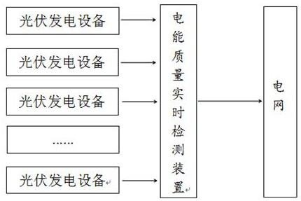
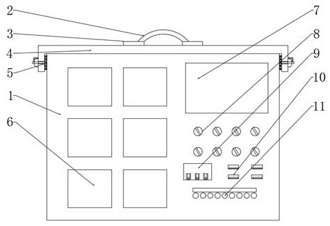
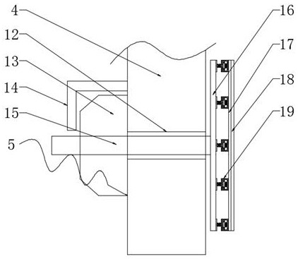
The invention discloses an electric energy quality real-time detection device, which is connected with a plurality of dispersed photovoltaic power generation devices at one side, and connected with apower grid at the other side. The plurality of dispersed photovoltaic power generation devices generate electric energy by using solar energy, the electric energy is transmitted to an electric energyquality real-time detection device through a network; after being detected by the electric energy quality real-time detection device, the electric energy is connected into the power grid. The electricenergy quality real-time detection device is characterized by comprising a device housing, a fixing plate, a sealing cover, a fixing assembly, an electric energy meter, a display screen, a rotary button, a USB interface and a power interface, a plurality of electric energy meters are arranged at one side of the center of one end of a shell; the top of the other side, located in the center, of oneend of the shell is sleeved with the display screen; and the rotary button is arranged at the bottom of the display screen and connected with the shell, and an operation valve is fixed to the bottomof the other side, located in the center, of one end of the shell through a screw. By adopts a clamping and fixing mode, free disassembly and replacement of parts in the electric energy quality real-time detection device are facilitated.

Description

technical field [0001] The invention relates to the technical field of power quality detection, in particular to a real-time power quality detection device. Background technique [0002] Distributed photovoltaic power generation technology is used more and more widely. This technology is to disperse solar power generation equipment on the roof of residential buildings, open ground, etc., and then connect the electric energy generated by each solar power generation equipment to the grid. Due to factors such as solar radiation and the stability of power generation equipment, the quality of power generated by various solar power generation equipment is uneven. If the quality of electric energy generated by each solar power generation device cannot be monitored in real time, the normal operation of the entire power grid may be affected, or even paralyzed. Historically, my country has caused huge economic losses due to the harmonic effects of distributed power generation. As an...

Claims


Application Information

Patent Timeline
Patent Type & Authority Patents(China)
IPC IPC(8): G01R1/04G01R31/00
Inventor 郝慎军陈祥龙胡明刘魁元时彦霞郑焕海周东凯梁周峰郭龙军贾凌云
Owner 日照阳光电力设计有限公司
Learn More