Shock-absorbing battery box for new energy automobiles

A technology for new energy vehicles and battery boxes, applied to secondary batteries, battery pack components, circuits, etc., can solve the problems of not being able to improve the heat dissipation effect, and achieve the effect of improving the heat dissipation effect and saving resources

Pending Publication Date: 2019-05-21
JILIN TEACHERS INST OF ENG & TECH
6 Cites 16 Cited by

AI-Extracted Technical Summary

Problems solved by technology

[0004] The invention provides a shock-absorbing battery box for a new energy vehicle, which can solve the problem th...

Method used

Described fixed plate 4 is all provided with shock pad 32 near the side of battery and described shock plate 31 near described battery, and the material of described shock pad 32 is rubber, further improves shock absorption Effect;
Further, described groove 21 is provided with shock-absorbing block 121, and the underside of described shock-absorbing block 121 is provided with spring, and described shock-absorbing block 121 is positioned at the below of described second support bar 12, and shock-absorbing block 121 The shock block 121 can effectively improve the shock absorption effect.
Should be provided with absorbent cotton in outlet pipe 7, reduce the humidity of air, guarantee the safety of battery;
The four sides and the bottom of fixed box 2 all have the spring that is connected on the battery box main body 1 inner wall, can well play damping effect, and the bottom of cover plate 3 is also provided with damping plate 31, can be fixed from The top of the box 2 acts as a shock absorber for the battery.
When the gear 13 rotates, the crankshaft 14 is driven to rotate, and the first connecting rod 15 is hinged at the curved position of the...

Abstract

The invention discloses a shock-absorbing battery box for new energy automobiles, belongs to the field of new energy automobile batteries and aims to solve the problem that a battery box in the priorart can play a shock absorbing effect but cannot improve the heat dissipation effect. The shock-absorbing battery box comprises a battery box main body and a fixing box arranged in the battery box main body, wherein a cover plate is arranged on the top of the battery box main body; a plurality of springs for absorbing shock of the fixing box are arranged on the inner wall of the battery box main body; an opening is formed in the top of the fixing box; fixing plates for clamping a battery are arranged on four sides of the inner wall of the fixing box; threaded rods are in threaded connection onthe side walls of the four sides of the fixing box; and the threaded rods respectively extend into one ends of the fixing box and are rotatably arranged on the fixing plates. The shock-absorbing battery box disclosed by the invention has the beneficial effects that a plurality of springs are arranged around the fixing box to play the role of shock absorption; and a heat dissipating mechanism forimproving the heat dissipating effect is also arranged and rubber airbags are pressed by pressure plates by utilizing the power potential energy brought by a shock absorbing component, so that the heat of the battery is dissipated and the resource is saved.

Application Domain

Secondary cellsCell component details

Technology Topic

Electrical batteryEngineering +5

Image

  • Shock-absorbing battery box for new energy automobiles
  • Shock-absorbing battery box for new energy automobiles
  • Shock-absorbing battery box for new energy automobiles

Examples

  • Experimental program(1)

Example Embodiment

[0024] A specific embodiment of the present invention will be described in detail below with reference to the accompanying drawings, but it should be understood that the protection scope of the present invention is not limited by the specific embodiments.
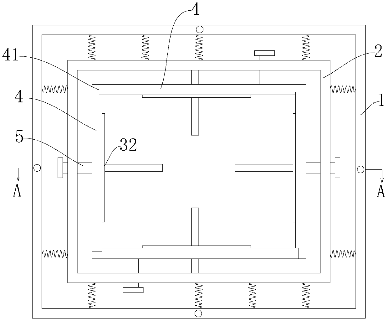
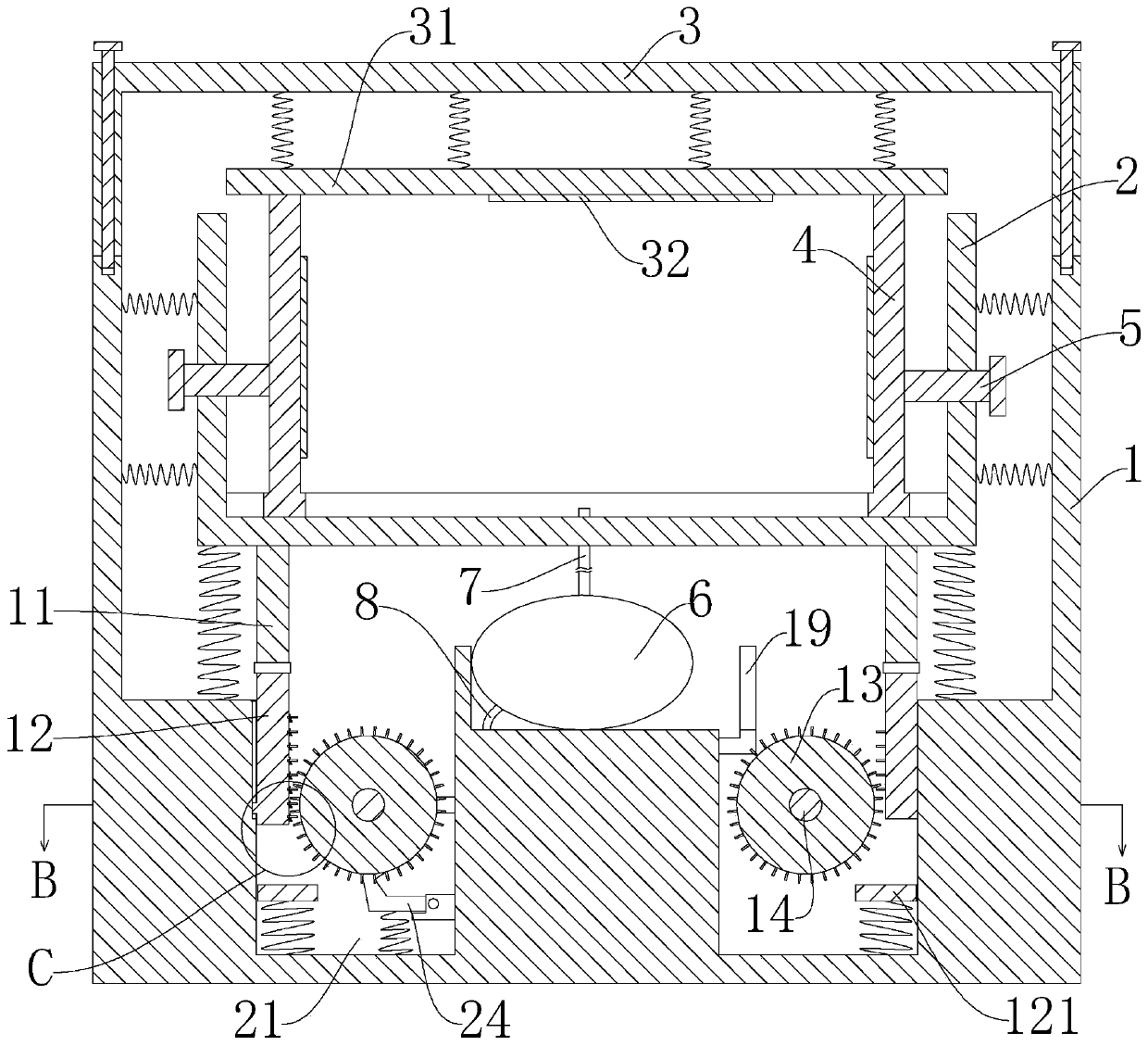
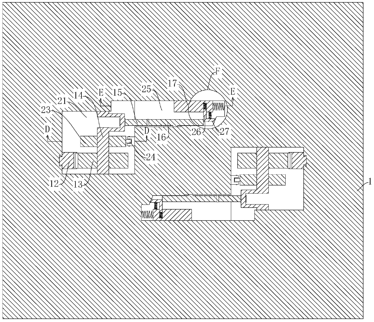
[0025] Such as Figure 1 to Figure 9 As shown, a shock-absorbing battery box for a new energy vehicle provided by an embodiment of the present invention includes a battery box body 1 and a fixed box 2 arranged in the battery box body 1, and a cover is provided on the top of the battery box body 1. The inner wall of the battery box body 1 is provided with a plurality of springs for damping the fixed box 2, the top of the fixed box 2 has an opening, and the four sides of the inner wall are provided with clamping The fixing plate 4 of the battery, the four side walls of the fixing box 2 are threadedly connected with threaded rods 5, and one end of the threaded rod 5 extending into the fixing box 2 is rotatably arranged on the fixing plate 4 , The bottom of the battery box body 1 is also provided with two rubber airbags 6, the rubber airbag 6 is provided with an air outlet pipe 7 and an air inlet pipe 8, the end of the air outlet pipe 7 away from the rubber airbag 6 is connected to In the fixed box 2, the end of the air inlet pipe 8 away from the rubber airbag 6 extends out of the battery box body 1;
[0026] It also includes a heat dissipation mechanism. The heat dissipation mechanism includes two heat dissipation groups. Each heat dissipation group includes a first support rod 11 fixedly installed at the bottom of the fixed box 2 and a second support rod 11 hinged to the first support rod 11. Two supporting rods 12, gear 13, crankshaft 14, first connecting rod 15 hinged at the bend of said crankshaft 14, inserting rod 16 hinged to said first connecting rod 15, ejector rod 17, second connecting rod 18 and For squeezing the top plate 19 of the rubber airbag 6, a groove 21 is opened at the bottom of the battery box body 1, a part of the second support rod 12 extends into the groove 21, and the second support One side of the rod 12 is hinged with a tooth plate 22 for driving the gear 13 to rotate. The upper side of the tooth plate 22 is provided with a top block 29 for restricting the rotation direction of the tooth plate 22. The side is provided with a spring for pressing the tooth plate 22 against the top block 29. The spring exerts a thrust on the tooth plate 22 to force the tooth plate 22 to abut against the top block 29, and the crankshaft 14 is rotatably arranged on the top block 29. In the groove 21, the crankshaft 14 is located at the center of the gear 13, and one side of the gear 13 is also provided with a ratchet 23 fixedly mounted on the crankshaft 14, and the inner wall of the groove 21 is also installed The pawl 24 matched with the ratchet wheel 23 drives the ratchet wheel 23 to rotate when the second support rod 12 moves downward, and when the second support rod 12 moves upward, the pawl 24 restricts the The ratchet wheel 23 rotates; the inner wall of the groove 21 is also provided with a slot 25, the slot 25 is provided with a strong spring connected to the top rod 17, the plug rod 16 and the top rod 17 are both It is slidably arranged in the slot 25, the top rod 17 is provided with a slot on one side close to the inserting rod 16, and a push plate 26 is connected in the slot through a spring, and the push plate 26 is close to the inserting rod 16. A connecting plate 27 is fixedly connected to one side of the bottom wall of the groove 25. The connecting plate 27 and the bottom of the slot 25 are both provided with guiding inclined surfaces. The top plate 19 is located on one side of the rubber airbag 6, and the top One end of the rod 17 is connected to the top plate 19 through the second connecting rod 18, and the bottom of the battery box main body 1 is provided with a relief groove 28 for giving way to the second connecting rod 18.
[0027] When the screw rod 5 is rotated, the screw rod 5 pushes the fixing plate 4 inward, thereby fixing the battery placed in the fixing box 2.
[0028] The four sides and bottom of the fixed box 2 have springs connected to the inner wall of the battery box main body 1, which can effectively absorb shock. The bottom of the cover plate 3 is also provided with a shock absorber 31, which can be removed from the fixed box 2 The upper part has a shock absorption effect on the battery.
[0029] When the car is driving on a bumpy road section, the fixed box 2 swayed up and down. During the swaying process, the second support rod 12 will be pressed down by the first support rod 11, from Figure 5 It can be seen that a slider is fixed on the second support rod 12, and the slider is slidably arranged on the side wall of the groove 21, that is, the second support rod 12 directly slides up and down along the side wall of the groove 21, When the second support rod 12 is inserted down, the insert plate 22 contacts the teeth of the gear 13 and drives the gear 13 to rotate. The gear 13 cannot be reversed under the action of the ratchet wheel 23 and the pawl 24. The insert plate 22 is hinged on One side of the second support rod 12 cannot be rotated upwards under the action of the top block 29, but it can be rotated downwards, so when the second support rod 12 moves up, the gear 13 will not hinder the second support rod 12 from moving upwards. After the second support rod 12 is moved up, the inserting plate 22 is restored to the level under the action of the spring.
[0030] When the gear 13 rotates, it drives the crankshaft 14 to rotate. The first connecting rod 15 is hinged at the position where the crankshaft 14 is bent. image 3 with Figure 4 It can be seen from the above that when the crankshaft 14 rotates, the second connecting rod 15 will drive the plunger 16 to reciprocate. When the plunger 16 is inserted in, it will interfere with the push plate 26, thereby pushing the ejector rod 17 inward. Under the action of the ratchet wheel 23 and the pawl 24, the strong spring cannot push the ejector pin 17 outward, and the plunger 16 pushes the ejector pin 17, so that the ejector pin 17 accumulates the potential energy of the spring deformation. In the process of pushing in, the connecting plate 27 When the inclined guide surface of the push plate is in contact with the inclined surface of the slot 25, the push plate 26 gradually retracts into the groove opened on the ejector rod 17, that is, the push plate 26 gradually separates from the plunger 16. When the push plate 26 separates from the plunger 16, the ejector Under the reaction force of the spring, the rod 17 quickly pushes outwards, and the top plate 19 is driven against the rubber airbag 6 through the second connecting rod 18, and the air in the rubber airbag 6 is sprayed toward the battery to improve the heat dissipation effect;
[0031] The air intake pipe 8 of the rubber airbag 6 is provided with a one-way valve, the outside air can enter the rubber airbag 6, and the air outlet pipe 7 is also provided with a one-way valve. The air in the rubber airbag 6 enters the fixed box 2 and is sent to the battery. The length of the air outlet pipe 7 and the air inlet pipe 8 has a margin to meet the shaking of the fixed box 2, and the nozzle extension position of the air inlet pipe 8 is not shown in the figure. A filter screen should be provided at the nozzle to remove dust;
[0032] There should be absorbent cotton in the air outlet pipe 7 to reduce the humidity of the air and ensure the safety of the battery;
[0033] When the spring pushes the rod 17 outward, one end of the insert rod 16 is located on the guide slope of the slot 25. When the push rod 17 is pushed outward, the push plate 26 will not be stuck at one end of the insert rod 16, but will interfere with the insert. On the side of the rod 16, the ejector rod 17 returns to the initial position after being pushed, the gear 13 continues to rotate under the shaking of the fixed box 2, the plunger 16 is pulled out under the drive of the crankshaft 14, when the plunger 16 is pulled out to the maximum Previously, the push plate 26 is located at one end of the plunger 16 under the action of the spring, and the plunger 16 can push the ejector 17 inward again.
[0034] A sliding block is also fixed on the inserting rod 16, which is slidably arranged in a sliding groove formed on the inner wall of the slot 25, that is, the inserting rod 16 can only move along the inner wall of the slot 25.
[0035] The housing of the fixed box 2 and the push plate 4 are provided with heat dissipation holes, but they are not shown in the figure.
[0036] Further, the two heat dissipation groups are centrally symmetrically arranged in the battery box main body 1, from image 3 with Figure 4 It can be seen that the centers of the two heat dissipation groups are symmetrical with the center of the battery box body 1 as the symmetrical point.
[0037] Further, a shock-absorbing block 121 is arranged in the groove 21, a spring is arranged on the lower side of the shock-absorbing block 121, the shock-absorbing block 121 is located below the second support rod 12, and the shock-absorbing block 121 Can effectively improve the shock absorption effect.
[0038] Further, the cover plate 3 is fixedly mounted on the top of the battery box main body 1 by bolts, and the lower side of the cover plate 3 is also connected with a shock absorbing plate 31 through a spring, and the shock absorbing plate 31 is in contact with the battery. Directly above;
[0039] The side of the fixing plate 4 close to the battery and the side of the shock-absorbing plate 31 close to the battery are both provided with a shock-absorbing pad 32, and the material of the shock-absorbing pad 32 is rubber to further improve the shock-absorbing effect;
[0040] Each of the fixing plates 4 is provided with a card slot 41 for clamping the adjacent fixing plate 4, and the position of the card slot 41 can be changed from figure 1 It can be seen that in order to allow the four fixing plates 4 to clamp each other, the size of the slot 41 should be designed according to the size of the battery to be fixed, so as to share the lateral force on the battery itself.
[0041] Working principle: When in use, open the cover 3, put the battery into the fixed box 2, twist the four threaded rods 5 to clamp the battery, and then fix the cover 3 with the battery box main body 1 by bolts, and drive in the car During the process, the fixed box 2 shook due to the bumps of the road, and the spring and the shock-absorbing plate 31 in the battery box main body 1 played the role of damping. During the shaking of the fixed box 2, the second support rod 12 would be pushed down. When the second support rod 12 moves downward, it will drive the gear 13 to rotate. The gear 13 drives the crankshaft 14 to rotate. The inserting rod 16 is inserted into the slot 25, and the ejector rod 17 is pushed inward through the push plate 26, and the wire is connected to the connecting plate 27. Under the action of the inclined plane, the push plate 26 is separated from the plunger 16, and the ejector rod 17 pushes outward under the reaction force of the strong spring, and the top plate 19 is driven by the second connecting rod 27 to squeeze the rubber airbag 6, and the gas in the rubber airbag 6 Spray to the battery to dissipate heat.
[0042] What has been disclosed above are only a few specific embodiments of the present invention, but the embodiments of the present invention are not limited thereto, and any changes that can be thought of by those skilled in the art should fall into the protection scope of the present invention.

PUM

no PUM

Description & Claims & Application Information

We can also present the details of the Description, Claims and Application information to help users get a comprehensive understanding of the technical details of the patent, such as background art, summary of invention, brief description of drawings, description of embodiments, and other original content. On the other hand, users can also determine the specific scope of protection of the technology through the list of claims; as well as understand the changes in the life cycle of the technology with the presentation of the patent timeline. Login to view more.

Similar technology patents

High-efficiency heat dissipation motor

Owner:陕西易盈电气科技工业有限公司

Welding and radiating turntable

Owner:WUXI UNITE ENERGY TECH CO LTD

Blast furnace cooling tuyere

Owner:常州市武进长虹结晶器有限公司 +1

Classification and recommendation of technical efficacy words

  • save resources
  • Improve cooling effect

Software test apparatus and test method

Owner:KINGDEE SOFTWARE(CHINA) CO LTD

Granular pesticide fertilizer, and preparation method and application thereof

InactiveCN102775241AReduce stress on the farm environmentsave resources
Owner:SHENZHEN NOPOSION AGROCHEM

Composite admixture for cement or high-performance concrete and preparation method thereof

InactiveCN102180612Asave resourcesgood social benefits
Owner:葫芦岛市辽西混凝土外加剂有限公司

Backlight unit

InactiveCN103336388AImprove cooling effecteven heat distribution
Owner:TCL CHINA STAR OPTOELECTRONICS TECH CO LTD

Novel air film hole with improved cooling efficiency

InactiveCN103452595AImprove cooling effectWide air-conditioning coverage
Owner:QINGDAO UNIV OF SCI & TECH

Water-cooled engine and cylinder cover thereof

ActiveCN103867332ATake away heat loadImprove cooling effect
Owner:ANHUI HUALING AUTOMOBILE

Power battery pack thermal management system and vehicle

ActiveCN108390123AImprove cooling effectreduce water temperature
Owner:FJ MOTOR GRP YUDO NEW ENERGY AUTOMOBILE CO LTD
Why Eureka
Try Eureka