Solar power generation system with automatic snow and dust removal function

A technology of power generation system and solar energy, applied in the field of solar power generation system, can solve the problems such as the influence of the output performance of the solar panel, the large amount of labor for removing the snow from the solar panel, and the reduction of the battery efficiency.

Active Publication Date: 2019-05-21
阜阳文鼎工艺品有限公司
View PDF10 Cites 4 Cited by
  • Summary
  • Abstract
  • Description
  • Claims
  • Application Information

AI Technical Summary

Problems solved by technology

[0002] The output performance of solar panels is affected by the dust deposited on the surface, which reduces the efficiency of the battery; dust has a direct impact on the solar irradiance received by the panel and heat dissipation, and can corrode the surface of the panel; in addition, under the influence of snowfall, if Continuous snowfall will lead to snow accumulation on solar panels, resulting in the inability to perform power generation operations. Manual snow removal on solar panels in snowy weather is labor-intensive and difficult to clean

Method used


Image

  • Solar power generation system with automatic snow and dust removal function
  • Solar power generation system with automatic snow and dust removal function
  • Solar power generation system with automatic snow and dust removal function

Examples


specific Embodiment approach 1

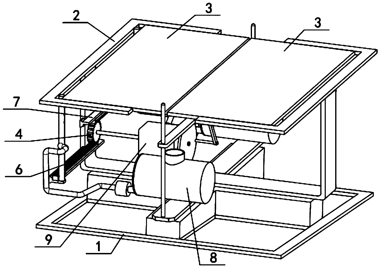
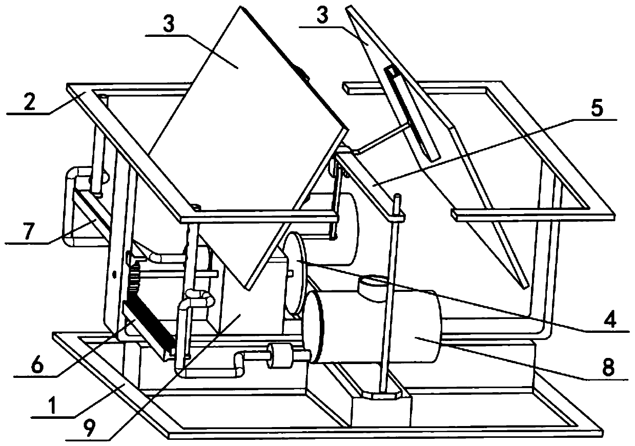
[0030] Such as Figure 1-10 As shown, the solar power generation system for automatic snow removal and dust removal includes a slope frame 1, a main frame 2, a solar panel 3, a brake mechanism 4, an adjustment structure 5, ash removal module I6, ash removal module II7 and a water supply module 8. The slope The main frame 2 is fixedly connected to the frame 1, two solar panels 3 are rotatably connected to the main frame 2, the brake mechanism 4 is fixedly connected to the main frame 2, the adjustment structure 5 is connected to the brake mechanism 4 in rotation, and the adjustment structure 5 The left and right ends are rollingly connected with two solar panels 3 respectively, the front and rear ends of the adjustment structure 5 are slidingly connected to the main frame 2, the ash removal module I6 and the ash removal module II7 are both engaged with the brake mechanism 4 for transmission, and the ash removal module Both the I6 and the ash removal module II7 are slidingly conn...

specific Embodiment approach 2

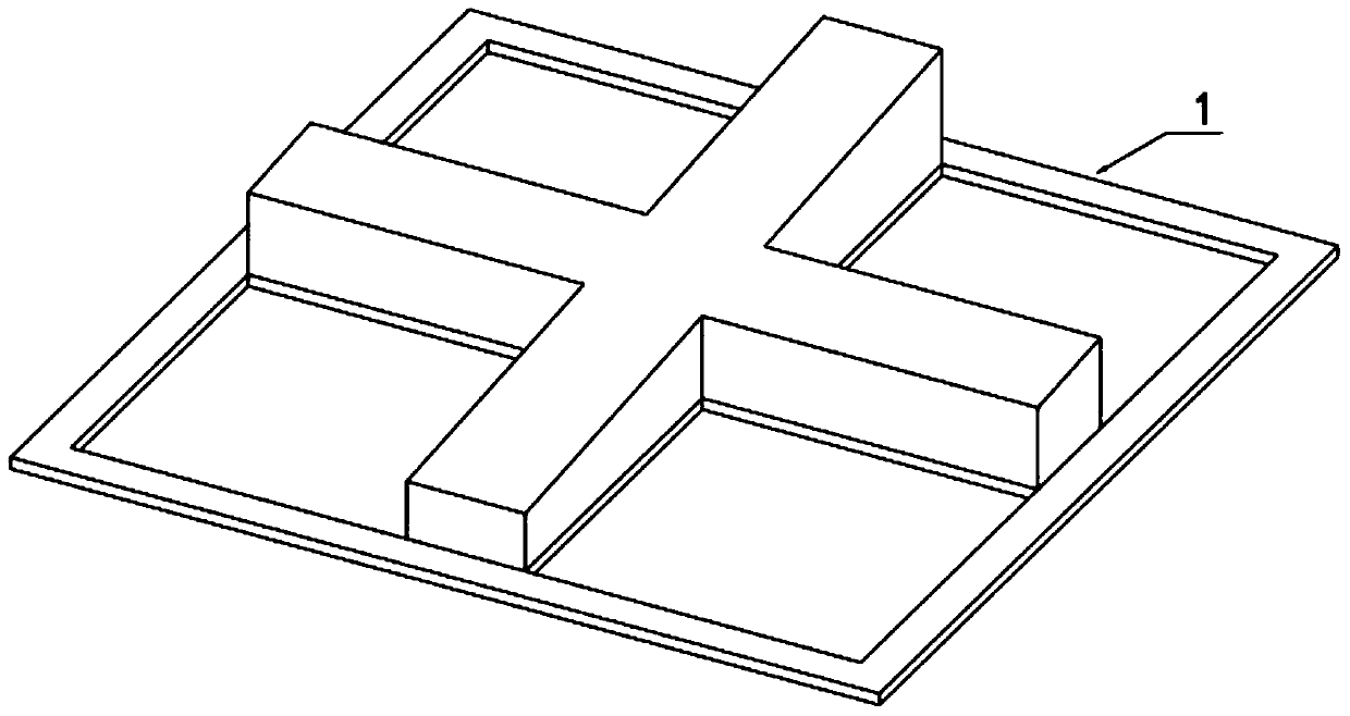
[0031] Such as Figure 1-10 As shown, the main frame 2 includes a cross base 2-1, a motor base 2-2, a guide rod 2-3, a top frame 2-4, a support shaft 2-5, a linear slideway 2-6 and a shaft hole I2 -7, the left side of the cross base 2-1 is fixedly connected with a motor base 2-2, the front and rear sides of the cross base 2-1 are fixedly connected with guide rods 2-3, and the two sides of the upper end of the cross base 2-1 Both are fixedly connected with a top frame 2-4, and the two top frames 2-4 are fixedly connected with a support shaft 2-5, and the inner side of the left end of the cross base 2-1 is provided with two linear slideways 2-6 and a shaft for The hole I2-7, the shaft hole I2-7 is located in the middle of the two linear slides 2-6; the cross base 2-1 is fixedly connected to the upper end of the inclined plane frame 1. The guide rod 2-3 is used to make the adjustment structure 5 more stable when it moves up and down.

specific Embodiment approach 3

[0032] Such as Figure 1-10As shown, the solar panel 3 includes a panel main body 3-1, a shaft hole II 3-2, a slide rail 3-3, a groove 3-4 for rollers and a strip opening 3-5, and the panel main body 3-1 The middle end is provided with a shaft hole II 3-2, and the lower end surface on the right side of the panel main body 3-1 is fixedly connected with a slide rail 3-3, and the slide rail 3-3 is provided with a groove 3-4 for rollers and a strip opening 3- 5. There are two solar panels 3; the two solar panels 3 are mirror images, and the two panel main bodies 3-1 are connected to the two supporting shafts 2-5 through the shaft holes II 3-2 respectively. superior. The panel main body 3-1 is a photovoltaic panel, i.e. a solar cell panel. If the shaft hole II 3-2 is inconvenient to be arranged on the panel main body 3-1, the slat structure can be fixed at the middle side of the lower end of the panel main body 3-1, and the The shaft hole II 3-2 can be set on the slat structure, ...


PUM


Abstract

The invention relates to power generation systems, in particular to a solar power generation system with an automatic snow and dust removal function. The system comprises a bevel frame, a main frame,two solar panels, a braking mechanism, an adjustment mechanism, a dust removal module I, a dust removal module II and a water supply module, wherein the adjustment mechanism capable of moving up and down in a reciprocating mode drives the two solar panels to shake left and right, and then accumulated snow is made to slip off the solar panels; a gear rotating forwards and backwards cyclically drives a rack I and a rack II to move close or apart cyclically so that water sprayed by a spray pipe I and a spray pipe II can completely cover a panel body at one side; and then the panel body at one side is tilted so that the water can carry away dust at the upper end of the panel body at one side while flowing away. The height of the spray pipe I and the spray pipe II is set according to the quantity of the systems in use, and cleaning of the solar panels at both sides through a single system or cleaning of a large-scale solar panel with least water resources through multiple systems can be realized.

Description

technical field [0001] The invention relates to a power generation system, more specifically a solar power generation system for automatic snow and dust removal. Background technique [0002] The output performance of solar panels is affected by the dust deposited on the surface, which reduces the efficiency of the battery; dust has a direct impact on the solar irradiance received by the panel and heat dissipation, and can corrode the surface of the panel; in addition, under the influence of snowfall, if Continuous snowfall will lead to snow accumulation on solar panels, resulting in the inability to perform power generation operations. Manual snow removal on solar panels in snowy weather is labor intensive and difficult to clean. Contents of the invention [0003] The purpose of the present invention is to provide a solar power generation system for automatic snow and dust removal, which can automatically remove snow and dust for solar panels. [0004] The purpose of the...

Claims


Application Information

Patent Timeline
IPC IPC(8): H02S40/10H02S40/12
CPCY02E10/50
Inventor 不公告发明人
Owner 阜阳文鼎工艺品有限公司
Why Eureka
Try Eureka