Solution film-forming method
A technology of solution film making and casting film, applied in the direction of flat products, household appliances, other household appliances, etc., can solve problems such as glass breakage, and achieve the effect of improving smoothness
- Summary
- Abstract
- Description
- Claims
- Application Information
AI Technical Summary
Problems solved by technology
Method used
Image

Examples
no. 1 Embodiment approach
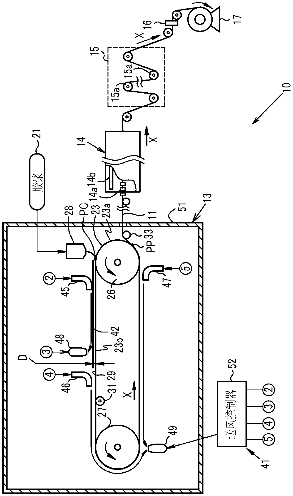
[0035] implement the present invention figure 1 The illustrated solution film forming apparatus 10 is used to produce an optical film (hereinafter, simply referred to as “film”) 11 . This film 11 constitutes an image display surface of a mobile terminal, that is, is used as an outermost protective film of a touch panel disposed on an image display portion. This film 11 can be used as a substitute instead of conventional glass, or can be used in a state of being attached to a glass surface. The thickness of the produced film 11 is in the range of 10 μm to 300 μm, preferably in the range of 100 μm to 300 μm, more preferably in the range of 150 μm to 250 μm. In this embodiment, it is set to 200 μm.
[0036] The solution film forming facility 10 includes a casting device 13 , a tenter 14 , a roll drying device 15 , a slitter 16 , and a winding device 17 in this order from the upstream side. In addition, in this specification, the solvent content rate (unit; %) is a value based ...
no. 2 Embodiment approach
[0084] In the second embodiment, a drum is used as a casting support. Below, refer to Figure 4 A second embodiment will be described. In the second embodiment, the drum 123 is used instead of the conveyor belt 23 , and the air supply drying unit 141 is used instead of the air supply drying unit 41 , and it is the same as the first embodiment except that. exist Figure 4 , labeled with Figure 1 ~ Figure 3 Components with the same reference numerals and the like are as described in the first embodiment, and thus description thereof will be omitted.
[0085] The casting device 113 includes a die 28 that discharges the dope 21 , and a drum 123 that is disposed below the die 28 and casts the dope 21 on the peripheral surface 123 a. A drive device (not shown) is connected to the drum 123, and a controller (not shown) is connected to the drive device. The drum 123 is driven to rotate around the rotating shaft 123b by a drive device controlled by a controller. Thus, the periph...
no. 3 Embodiment approach
[0098] refer to Figure 5 and Image 6 A third embodiment will be described. A third embodiment of the present invention is an embodiment in which a wind shielding member is provided in the second embodiment. The third embodiment is the same as the second embodiment except that a windshield member is provided. Figure 5 and Image 6 , labeled with Figure 1 ~ Figure 4 Components and the like having the same reference numerals are as described in the second embodiment, and thus description thereof will be omitted.
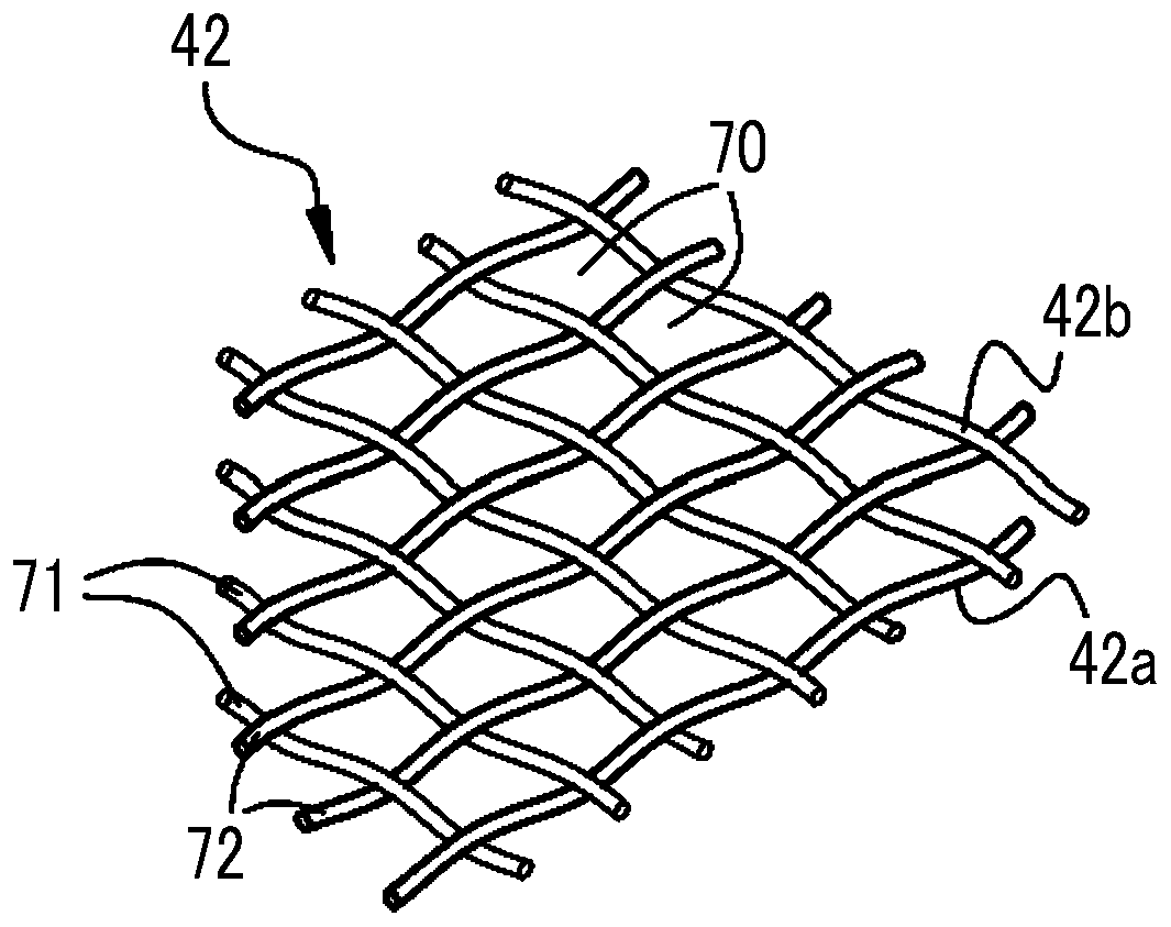
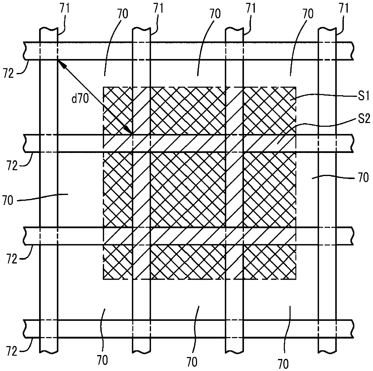
[0099] The windshield member is arranged in a state facing the edge 42c, 42d, 42e, 42f of the net 42 and in a state protruding toward the drum 123 side than the net 42 . Additionally, if Image 6 As shown, the edge 42c and the edge 42d are the edge of the net 42 in the width direction Y, ie, the side edge. and, if Figure 5 As shown, the end edge 42f is the upstream edge of the wire 42 in the traveling direction X. As shown in FIG. The wind blocking member ...
PUM
| Property | Measurement | Unit |
|---|---|---|
| Thickness | aaaaa | aaaaa |
| Diameter | aaaaa | aaaaa |
Abstract
Description
Claims
Application Information