Embossing tool for deforming smooth and embossed films

A tooling, smoothing technology applied in the area of ​​imprinting dies, which can solve problems such as imprinting and stamping device wear

Active Publication Date: 2019-05-21
BERHALTER
View PDF9 Cites 0 Cited by
  • Summary
  • Abstract
  • Description
  • Claims
  • Application Information

AI Technical Summary

Problems solved by technology

In order to achieve a somewhat acceptable result, i.e. smooth areas, this requires

Method used


Image

  • Embossing tool for deforming smooth and embossed films
  • Embossing tool for deforming smooth and embossed films
  • Embossing tool for deforming smooth and embossed films

Examples


Embodiment Construction

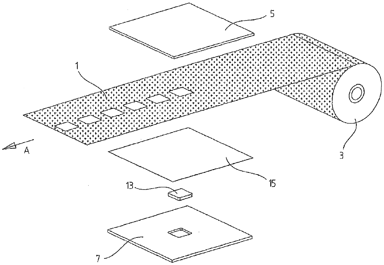
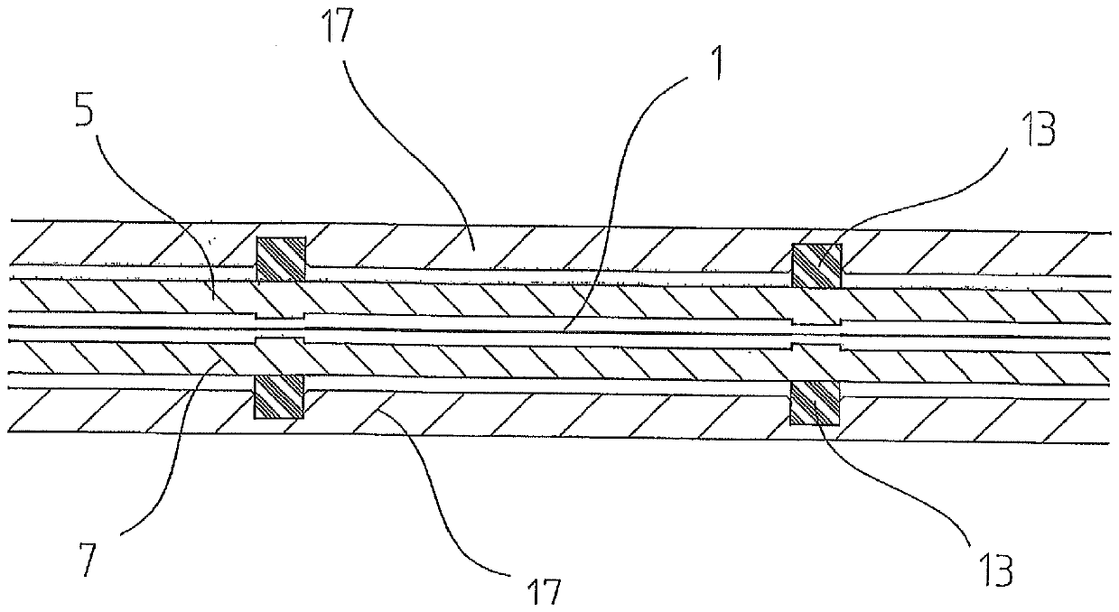
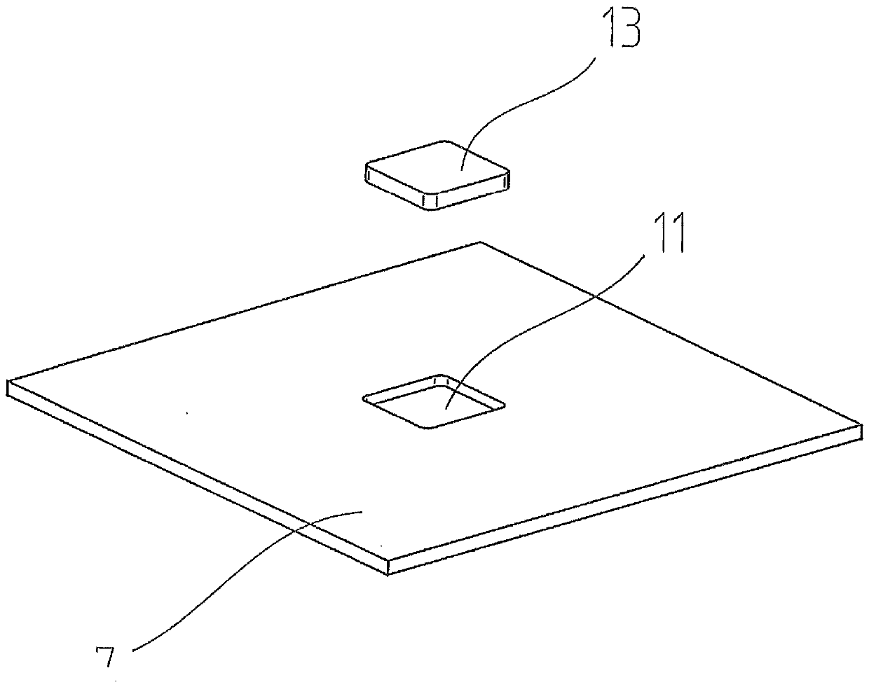
[0020] exist figure 1 In the schematic diagram in , the mold, that is to say the device for removing or eliminating the embossing of selected areas on the embossed film 1 , is shown in an exploded view. Above the film 1 which can be passed from the reel 3 between the die or die plate 5 and the die or receiving plate 7, a projection is formed on the underside of the die 5, here with a smooth surface The raised 9. The cross-section of this protrusion 9 corresponds to the surface on the already embossed film that should eliminate embossing, that is to say, the surface of the film 1 should be deformed completely smoothly again ( figure 2 ). A compensating element 13 is inserted in the groove 11 in the plunger 7 . The compensating element 13 protrudes a few tenths of a millimeter from the surface of the male mold 7 . The cross section of the compensating element 13 substantially corresponds at least to the cross section of the projection 9 in the die 5 .

[0021] The compensa...


PUM


Abstract

The invention relates to an embossing tool comprising a female die (5) and a male die (7). An elevation (9) is formed on the female die, which corresponds to the area to be embossed. An elastic compensating element (13) is located in a recess (11) of the male die (7), which protrudes the surface of the male die (7) by a few tenths of a millimeter. This embossing tool allows elimination of existingembossments on a film (1).

Description

technical field [0001] The invention relates to an embossing tool for deforming smooth and embossed films according to the preamble of claim 1 . Background technique [0002] Film made of metal or laminate, mostly aluminum, used in the packaging industry for closing half-filled food containers such as yoghurt cups, but also for closing coffee capsules or sachets for commercial enterprises and can be used For other applications, the laminate consists of metal and plastic or paper. A blank formed on the container corresponding to the opening to be closed is punched out of this film and stacked for subsequent processing, that is to say for the closure. Embossed parts made of a smooth film cause problems during subsequent processing, especially when capping, because they stick to each other and therefore cannot be separated or can only be separated incorrectly. This results in rejects on the filler and capper. For a long time, therefore, stampings have usually been provided f...

Claims


Application Information

Patent Timeline
IPC IPC(8): B31F1/07B31B50/88
CPCB21D1/06B21D22/10B21D24/02B31F1/07B31F2201/0702B31B50/88B21D22/04B32B15/08B32B38/06B31B50/142
Inventor D.楚曼M.斯坦内
Owner BERHALTER
Why Eureka
Try Eureka