Method for Identifying Phase Difference Between Inlet Valve Stroke and Outlet Valve Stroke of Internal Combustion Engine

A technology of phase difference and outlet valves, applied in the direction of internal combustion piston engines, combustion engines, valve devices, etc.

Active Publication Date: 2021-12-31
VTESCO TECH GMBH
View PDF10 Cites 0 Cited by
  • Summary
  • Abstract
  • Description
  • Claims
  • Application Information

AI Technical Summary

Problems solved by technology

Specific conclusions about valve control timing and piston stroke position of internal combustion engines cannot be easily drawn by means of this method either

Method used


Image

  • Method for Identifying Phase Difference Between Inlet Valve Stroke and Outlet Valve Stroke of Internal Combustion Engine
  • Method for Identifying Phase Difference Between Inlet Valve Stroke and Outlet Valve Stroke of Internal Combustion Engine
  • Method for Identifying Phase Difference Between Inlet Valve Stroke and Outlet Valve Stroke of Internal Combustion Engine

Examples


Embodiment Construction

[0071] The present invention is based on following recognition:

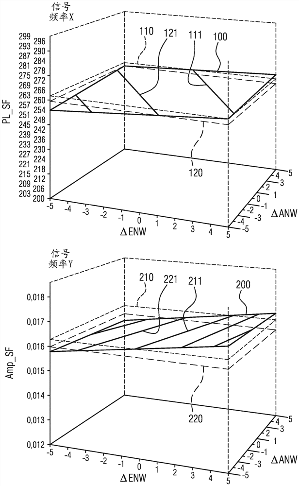
[0072] When the inlet valve stroke phase difference ∆EVH and the outlet valve stroke phase difference ∆AVH on the "ideal" reference internal combustion engine are changed, and when the pressure oscillation signal in the air intake port (hereinafter simply referred to as the pressure oscillation signal) by When the discrete Fourier analysis is analyzed, and taking into account the individually selected signal frequencies (which in each case correspond to the intake frequency or a multiple of the intake frequency), it has been found that the phase positions of the individually selected signal frequencies Both the magnitude and magnitude (that is, the relative position of the pressure oscillation signal to the crankshaft phase angle signal and the magnitude of the signal stroke) depend on the inlet valve stroke phase difference ∆EVH and on the outlet valve stroke phase difference ∆AVH.

[0073] image 3 This depen...


PUM


Abstract

The invention relates to a method for the combined identification of the inlet valve stroke difference and the outlet valve stroke difference of cylinders of an internal combustion engine, and said method is based on the fact that the intake air in the air intake duct can be distributed to the corresponding The dynamic pressure oscillation of the cylinder obtains the phase position and magnitude of the selected signal frequency of the pressure oscillation relative to the crankshaft phase angle signal. Based on these phase positions and magnitudes, the inlet valve travel phase difference and the outlet valve travel phase difference are then determined by using equal phase position lines and equal magnitude lines. A particularly precise identification of the control timing can thus be carried out in a simple and inexpensive manner, whereby advantages with regard to emissions, consumption, running smoothness and performance of the engine as well as improved closed-loop and open-loop controllability can be achieved.

Description

technical field [0001] The invention relates to a method by means of which the phase difference of the valve strokes of the inlet and outlet valves of a reciprocating piston internal combustion engine can be identified during operation in a combined form by evaluating the dynamic pressure oscillations of the intake air, in the air The dynamic pressure oscillations are measured in the intake tract. Background technique [0002] Reciprocating-piston internal combustion engines, which will also be referred to simply as internal combustion engines hereinafter, have one or more cylinders, in each case one reciprocating piston being arranged in the cylinder. To illustrate the principle of a reciprocating piston internal combustion engine, reference will be made below to figure 1 , which shows by way of example the cylinders and the most important functional units of an internal combustion engine, which may also be a multi-cylinder internal combustion engine. [0003] The respect...

Claims


Application Information

Patent Timeline
Patent Type & Authority Patents(China)
IPC IPC(8): F02D41/00F02D41/24F02D41/28F02D41/14F02D13/02F01L13/00F02D13/00
CPCF02D41/009F02D41/2432F02D41/28F02D13/0219F02D41/0002F02D2041/001F02D2041/1433F02D41/2464F02D2041/288F02D2200/0406F01L1/34F01L2001/34496F01L2800/14F01L2820/041F01L2820/042Y02T10/12Y02T10/40F01L13/0015F01L2800/11F01L1/344F01L2820/043F02D41/1401F02D2200/024
Inventor T.布劳恩
Owner VTESCO TECH GMBH
Why Eureka
Try Eureka