Combination method for identifying internal combustion engine piston, inlet valve and outlet valve stroke phase difference

A technology of piston stroke and phase difference, which is applied in the field of combined identification of internal combustion engine piston, inlet valve and outlet valve stroke phase difference, and can solve problems that cannot be easily made

Active Publication Date: 2021-06-18
VTESCO TECH GMBH
View PDF10 Cites 0 Cited by
  • Summary
  • Abstract
  • Description
  • Claims
  • Application Information

AI Technical Summary

Problems solved by technology

Certain conclusions about the valve control timing and piston stroke position of an internal combustion engine cannot easily be drawn by means of this method either

Method used


Image

  • Combination method for identifying internal combustion engine piston, inlet valve and outlet valve stroke phase difference
  • Combination method for identifying internal combustion engine piston, inlet valve and outlet valve stroke phase difference
  • Combination method for identifying internal combustion engine piston, inlet valve and outlet valve stroke phase difference

Examples


Embodiment Construction

[0067] The present invention is based on following recognition:

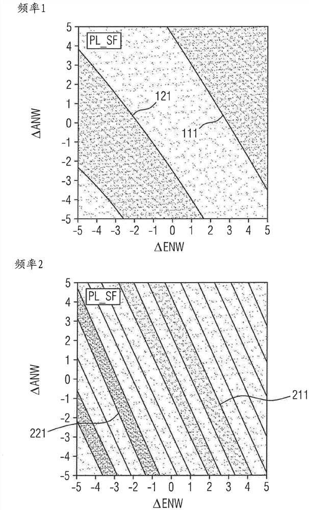
[0068] When varying the inlet valve stroke phase difference ΔEVH and the outlet valve stroke phase difference ΔAVH on an "ideal" reference internal combustion engine and analyzing the intake air in the air intake passage or the exhaust outlet passage by means of discrete Fourier analysis The pressure oscillation signal of the exhaust gas (hereinafter simply referred to as the pressure oscillation signal), and considering each individual selected signal frequency (in each case, each individual selected signal frequency corresponds to the intake frequency or the frequency of the intake frequency multiples), it was found, in particular, that the phase position of each individual selected signal frequency, that is, the relative position of the pressure oscillation signal relative to the crankshaft phase angle signal, depends on the inlet valve stroke phase difference ΔEVH and the outlet valve stroke phase difference ...


PUM


Abstract

A method for combined identification of piston stroke phasing, inlet valve phasing and outlet valve phasing of cylinders of an internal combustion engine wherein, during operation, intake air in an air intake passage and / or exhaust outlet passage The dynamic pressure oscillations in the exhaust gas assignable to the cylinders are measured, and wherein, based on the phase positions of the measured pressure oscillations for each selected signal frequency, iso-phase position lines are determined, and the iso-phase position lines are determined by projecting and phase The offset is brought to a common point of intersection, from which the inlet valve travel phase difference and the outlet valve travel phase difference and the piston travel phase difference are determined. As a result, a particularly precise identification of the control timing can be carried out in a simple and inexpensive manner, whereby advantages with regard to emissions, consumption, running smoothness and performance as well as improvements in the closed-loop and open-loop controllability of the engine can be achieved.

Description

technical field [0001] The invention relates to a method by means of which, by evaluating the dynamic pressure oscillations of the intake air and / or exhaust gas, it is possible to identify in combination the phase difference of the piston strokes of a reciprocating-piston internal combustion engine during operation, the valve of the inlet valve The stroke phase difference and the valve stroke phase difference of the outlet valve, the oscillations are measured in the air intake tract and in the exhaust outlet tract respectively. Background technique [0002] A reciprocating-piston internal combustion engine (hereinafter also to be referred to only in shortened form as an internal combustion engine) has one or more cylinders, in each case one reciprocating piston being arranged in one or more cylinders. In order to illustrate the principle of reciprocating piston internal combustion engine, the following will refer to figure 1 , figure 1 The cylinders and also the most impor...

Claims


Application Information

Patent Timeline
Patent Type & Authority Patents(China)
IPC IPC(8): F02D41/24F02D41/00F02D41/28
CPCF02D41/009F02D41/2432F02D41/0002F02D2041/001F02D41/2464F02D2041/288F02D2200/0406F02D41/28Y02T10/12Y02T10/40F02D41/3005
Inventor T.布劳恩J.凯因茨
Owner VTESCO TECH GMBH
Why Eureka
Try Eureka