Prediction of remaining useful lifetime for bearings

An effective life and bearing technology, which is applied in mechanical bearing testing, mechanical component testing, machine/structural component testing, etc., can solve problems such as troublesome monitoring and difficulty in accurately predicting the remaining effective life of pod-type azimuth thruster bearings, etc. Achieve the effect of avoiding unplanned downtime and minimizing maintenance costs

Active Publication Date: 2019-05-21
ABB (SCHWEIZ) AG
View PDF4 Cites 0 Cited by
  • Summary
  • Abstract
  • Description
  • Claims
  • Application Information

AI Technical Summary

Problems solved by technology

Such monitoring can be cumbersome and therefore it may be difficult to accurat

Method used


Image

  • Prediction of remaining useful lifetime for bearings
  • Prediction of remaining useful lifetime for bearings
  • Prediction of remaining useful lifetime for bearings

Examples


Embodiment Construction

[0030] The inventive concepts now will be described more fully hereinafter with reference to the accompanying drawings, in which certain embodiments of the inventive concepts are shown. However, inventive concepts may be embodied in many different forms and should not be construed as limited to the embodiments set forth herein; rather, these embodiments are provided by way of example so that this disclosure will be thorough and complete, and the present invention The scope of the concept is fully conveyed to those skilled in the art. Like reference numerals refer to like elements throughout the specification. Any steps or features shown in dashed lines should be considered optional.

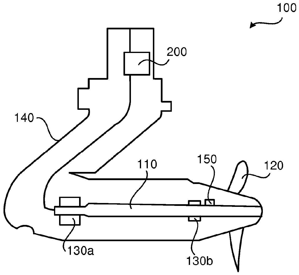
[0031] In practice, the true lifetime of a component may be random in nature. As a result, large amounts of field data may be required in order to develop appropriate forecasting methods. In many cases, such data are not available. The azimuth thruster disclosed above is an exception to this ...


PUM


Abstract

There is provided mechanisms for predicting remaining useful lifetime of a bearing of an electric podded azimuth thruster. A method is performed by a controller. The method comprises obtaining operational conditions of the bearing. The method comprises predicting the remaining useful lifetime of the bearing using the operational conditions. The lifetime of the bearing is divided in three separatephases. The remaining useful lifetime of the bearing is predicted differently in the three separate phases.

Description

technical field [0001] Embodiments presented herein relate to methods, controllers, computer programs and computer program products for predicting the remaining useful life of a bearing. Background technique [0002] In general, electric podded azimuth thrusters are marine propulsion units consisting of a fixed-pitch propeller mounted on a large steerable gondola ("the gondola") that also contains a motor to drive the propeller electric motor. Thus, a podded azimuth thruster combines the actions of rudder, thruster and propeller into one rotary propulsion unit. In a podded azimuth thruster unit, the electric motor is mounted inside the propulsion unit and the propeller is directly connected to the motor shaft. By avoiding the use of conventional propeller shafts, the propeller can be positioned further below the stern in clear water, providing greater hydrodynamic and mechanical efficiency. Further, it increases the flexibility of the general layout of the ship's power st...

Claims


Application Information

Patent Timeline
IPC IPC(8): G01M13/04G01M13/045
CPCG01M13/04
Inventor K·萨里南S·桑德-塔瓦莱伊
Owner ABB (SCHWEIZ) AG
Why Eureka
Try Eureka