
A test module for a fingerprint sensing device

A technology for testing modules and sensing devices, applied in the directions of measuring devices, measuring device casings, electronic circuit testing, etc., to achieve the effects of improving functional testing, accurate testing, and simplifying manufacturing

Active Publication Date: 2019-05-21
指纹卡安娜卡敦知识产权有限公司
View PDF6 Cites 1 Cited by
  • Summary
  • Abstract
  • Description
  • Claims
  • Application Information

AI Technical Summary

Problems solved by technology

[0003] Although fingerprint sensors are usually manufactured in high volumes with high manufacturing precision and high yields, the produced sensors still need to be tested, thus requiring efficient and automated testing procedures

Method used


Image

  • A test module for a fingerprint sensing device
  • A test module for a fingerprint sensing device
  • A test module for a fingerprint sensing device

Examples


Embodiment Construction

[0038] In the detailed description presented, various embodiments of systems and methods according to the present invention are described primarily with reference to capacitive fingerprint sensing devices. However, the described invention may also be applicable to other types of fingerprint sensing devices, such as ultrasonic or optical fingerprint sensing devices.

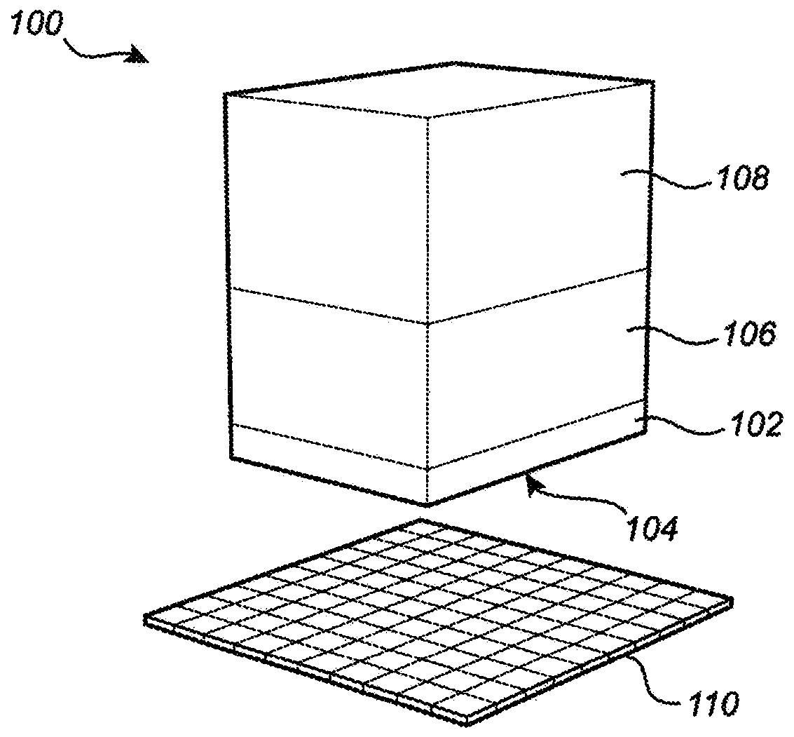
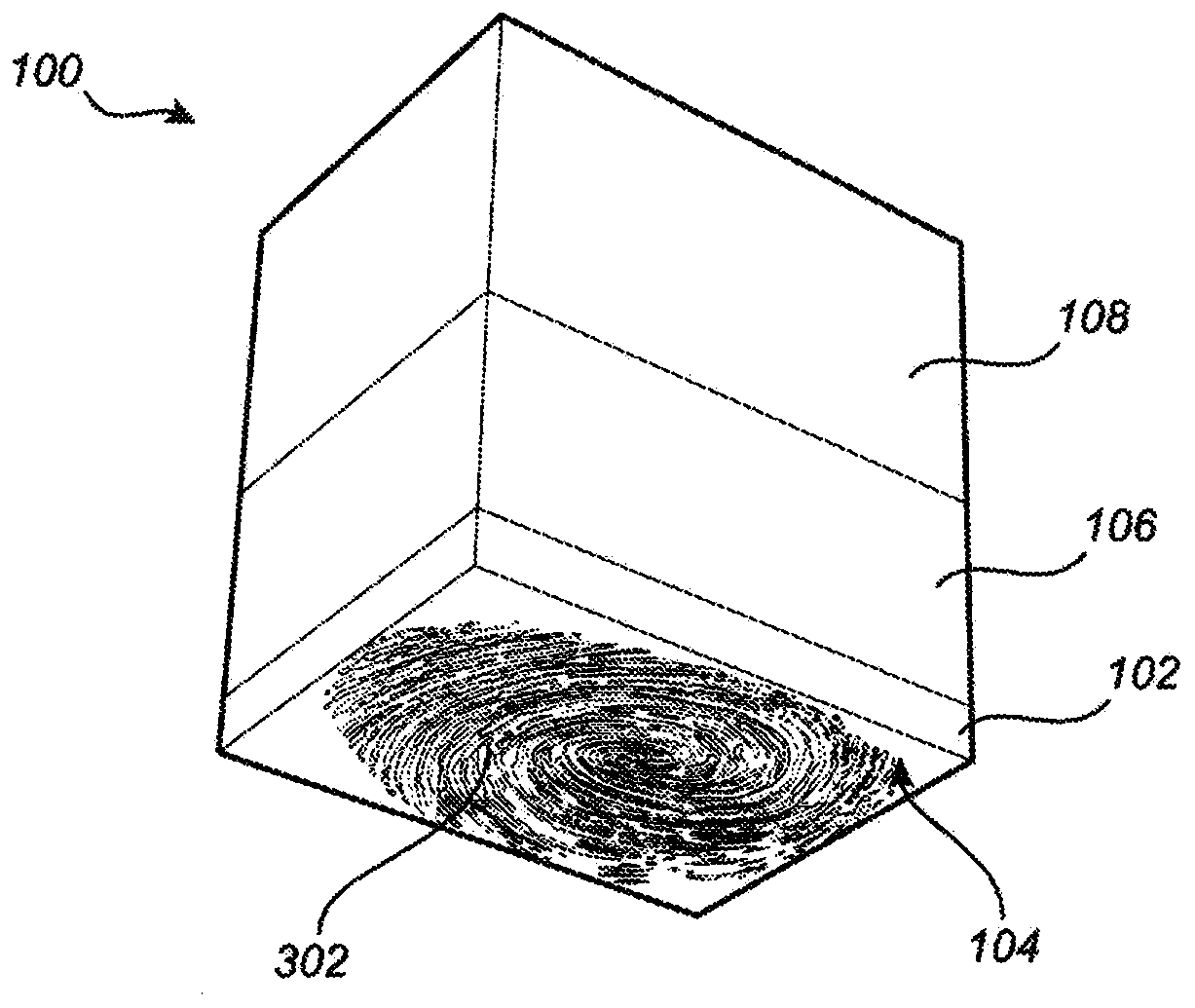
[0039] figure 1 A test module 100 according to an embodiment of the invention is schematically shown. The test module comprises an electrically conductive bottom element 102 comprising an outer surface portion 104 configured to be in contact with a sensing surface of a fingerprint sensing device 110 . The outer surface portion 104 thus refers to the bottom surface of the test module 100 , ie the surface facing the fingerprint sensing device 110 .

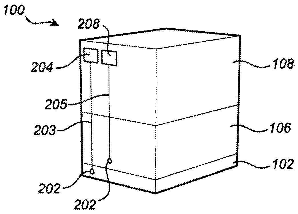
[0040] The test module 100 further comprises an electrically conductive intermediate element 106 connected to the bottom element 102 on the side opposite to the outer...


PUM


Abstract

There is provided a test module (100) for testing a fingerprint sensing device (110) comprising: an electrically conductive bottom element (102) comprising an exterior surface portion configured to contact a sensing surface of the fingerprint sensing device; an electrically conductive intermediate element(106), connected to the bottom element on a side opposing the exterior surface, the intermediate element comprising a flexible material enabling the bottom element to change alignment in response to an applied force occurring when the exterior surface is pressed against a surface being tiltedwith respect to the exterior surface of the bottom element; and a top element (108) configured connect the test module to a test fixture. There is alsoprovided a method for testing a fingerprint sensing device using the described test module.

Description

technical field [0001] The invention relates to a test module for testing a fingerprint sensing device. Background technique [0002] Biometric sensors, such as fingerprint sensors, are becoming more common in a variety of applications, such as computers, smart phones, smart cards, and other applications requiring biometric authentication. In particular, capacitive fingerprint sensors have been shown to provide accurate performance while being cost-effective and suitable for large-scale fabrication. [0003] Although fingerprint sensors are usually mass-produced with high manufacturing precision and high yields, the produced sensors still need to be tested, thus requiring efficient and automated testing procedures. Furthermore, in order to replicate the normal operating conditions of the sensor, when the sensor is tested it needs to be performed using a test structure that resembles a human finger as much as possible. [0004] In particular, the fingerprint sensor needs to...

Claims


Application Information

Patent Timeline
IPC IPC(8): G01R31/28G01D1/18G01R1/04G01R1/06G06K9/00G06V40/13G06V10/98G06V40/12
CPCG06V40/13G06V10/98G06V40/1394G06V40/1306A61B2562/0233G01R35/007
Inventor 彼得·奥斯特伦
Owner 指纹卡安娜卡敦知识产权有限公司
Learn More