A dust removal device for the production of new energy solar panels

A technology of solar panels and dust removal devices, applied in the direction of cleaning methods and tools, cleaning methods using tools, chemical instruments and methods, etc., can solve problems such as residues, artificial wiping efficiency underground, cleaning is not clean, etc., to achieve novel ideas and improve Dust removal quality and efficiency, the effect of ingenious structure

Active Publication Date: 2020-09-22
晶海洋半导体材料(东海)有限公司
View PDF5 Cites 1 Cited by
  • Summary
  • Abstract
  • Description
  • Claims
  • Application Information

AI Technical Summary

Problems solved by technology

[0002] During the production process, the surface of solar panels is often contaminated with dust and oil. If it is not cleaned, it will cause a decrease in power and affect the efficiency of use. It is often necessary to clean the surface of solar panels
[0003] Most of the current cleaning is done by manual wiping, or by wind blowing. Manual wiping is less efficient and takes up a lot of labor. High-pressure gas is used for blowing cleaning, which can only clean the residual particles on the surface, but for some adhesive Larger fine particles and oil stains cannot be cleaned, and the cleaning is not thorough
[0004] In the process of cleaning oil stains, a special cleaning solution is required. The cleaning solution should be used in an appropriate amount. If it is used too much, it will leave residue on the surface and cause waste. If it is used too little, the cleaning will not be clean.

Method used


Image

  • A dust removal device for the production of new energy solar panels
  • A dust removal device for the production of new energy solar panels
  • A dust removal device for the production of new energy solar panels

Examples


Embodiment Construction

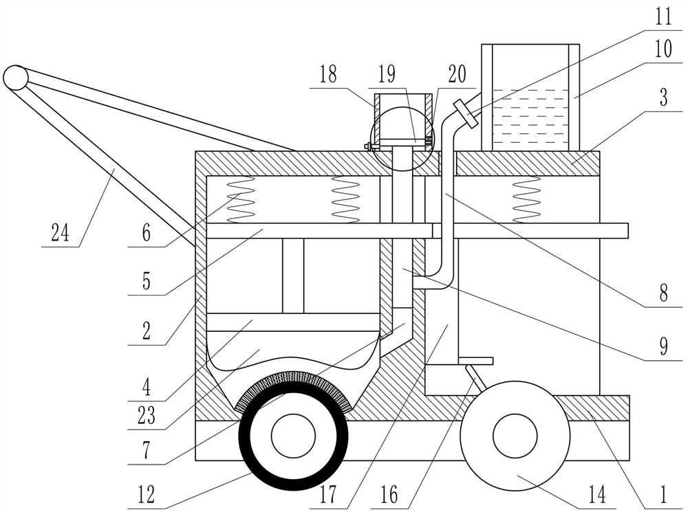
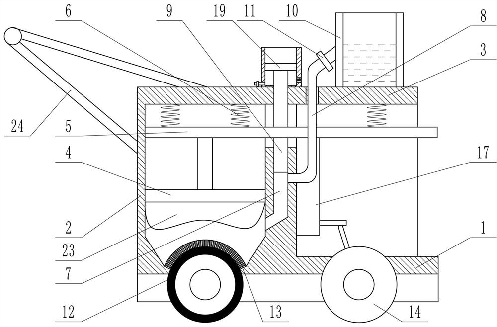
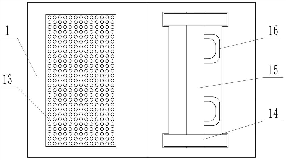
[0016] The specific implementation manners of the present invention will be described in further detail below in conjunction with the accompanying drawings.

[0017] Depend on Figure 1-6 It can be seen that the present invention includes a horizontally placed base plate 1, a vertically placed box body 2 is provided above the base plate 1, and a top plate 3 parallel to the bottom plate 1 is provided on the top of the box body 2, and the bottom plate 1 and the top plate 3 are larger than the box body. 2, the box body 2 is provided with a first piston 4 that can move up and down in the box body 2, and a push plate 5 is connected above the first piston 4, and the right end of the push plate 5 runs through the right side wall of the box body 2 A spring 6 is connected between the push plate 5 and the top plate 3, the upper end of the right side wall of the box body 2 is provided with a groove 7 with an upper end opening, the bottom of the groove 7 communicates with the inside of th...


PUM


Abstract

The invention provides a dust removal device for production of new energy solar panels. The wiping effect on the solar panels is well achieved, meanwhile, the using number of materials is effectivelycontrolled, and the dust removal quality and efficiency can be improved. According to the technical scheme, the dust removal device comprises a bottom plate, a box body is arranged on the upper part of the bottom plate, a top plate is arranged at the top of the box body, a first piston is arranged in the box body, the upper part of the first piston is connected with a pushing plate, springs are connected between the pushing plate and the top plate, a groove is formed in the upper end of the right side wall of the box body, the side wall of the upper part of the groove communicates with a feeding pipe, the lower part of the pushing plate is connected with a baffle, the pushing plate can move downwards under the effect of the springs, the upper end of the top plate is connected with a storing box, the upper end of the feeding pipe penetrates through the pushing plate to be connected with the storing box, and the feeding pipe is connected with a valve body; and the bottom of the box bodyis of a circular-arc-shaped structure, sweeping idler wheels are arranged on the lower part of the box body, the sweeping idler wheels and the circular-arc-shaped structure at the bottom of the box body are attached, and a plurality of small holes are formed in the bottom of the box body. The dust removal device is novel in concept and ingenious in structure.

Description

technical field [0001] The invention relates to the technical field of solar panel dust removal, in particular to a dust removal device for new energy solar panel production. Background technique [0002] During the production process, the surface of the solar panel is often contaminated with dust and oil. If it is not cleaned, the power will be reduced and the efficiency will be affected. It is often necessary to clean the surface of the solar panel. [0003] Most of the current cleaning is done by manual wiping, or by wind blowing. Manual wiping is less efficient and takes up a lot of labor. High-pressure gas is used for blowing cleaning, which can only clean the residual particles on the surface, but for some adhesive Larger fine particles and oil stains cannot be cleaned, and the cleaning is not thorough. [0004] In the process of cleaning oil stains, a special cleaning solution is required. The cleaning solution should be used in an appropriate amount. If it is used t...

Claims


Application Information

Patent Timeline
Patent Type & Authority Patents(China)
IPC IPC(8): B08B1/04H02S40/10
CPCY02E10/50
Inventor 朱琨薛纪超徐启程路素青刘朝中刘德波赵新莉
Owner 晶海洋半导体材料(东海)有限公司
Why Eureka
Try Eureka