
Cellosilk cutting device

A fiber cutting technology, which is applied in the field of fiber cutting devices, can solve problems such as jamming and cutting, and achieve the effects of easy replacement, convenient operation and smooth cutting

Pending Publication Date: 2019-05-24
ZHONGSHAN ZHENDEMEI PRECISION MASCH CO LTD
View PDF0 Cites 3 Cited by
  • Summary
  • Abstract
  • Description
  • Claims
  • Application Information

AI Technical Summary

Problems solved by technology

[0003] The purpose of the present invention is to overcome the deficiencies of the prior art, and propose a fiber cutting device, which can effectively solve the problem of knife hitting and jamming when multiple fibers are continuously conveyed and cut at high speed

Method used


Image

  • Cellosilk cutting device
  • Cellosilk cutting device
  • Cellosilk cutting device

Examples


Embodiment Construction

[0018] The present invention will be further described below in conjunction with specific examples.

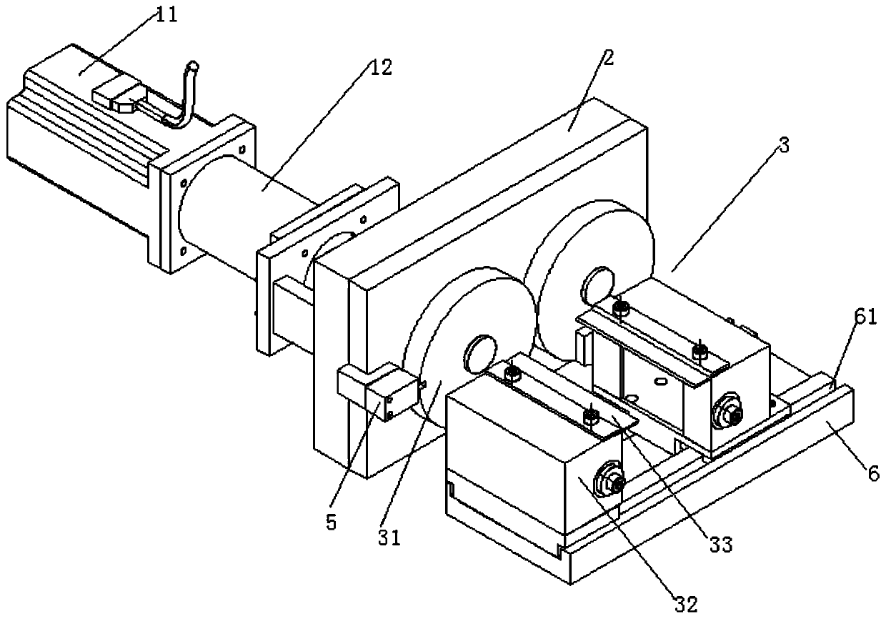
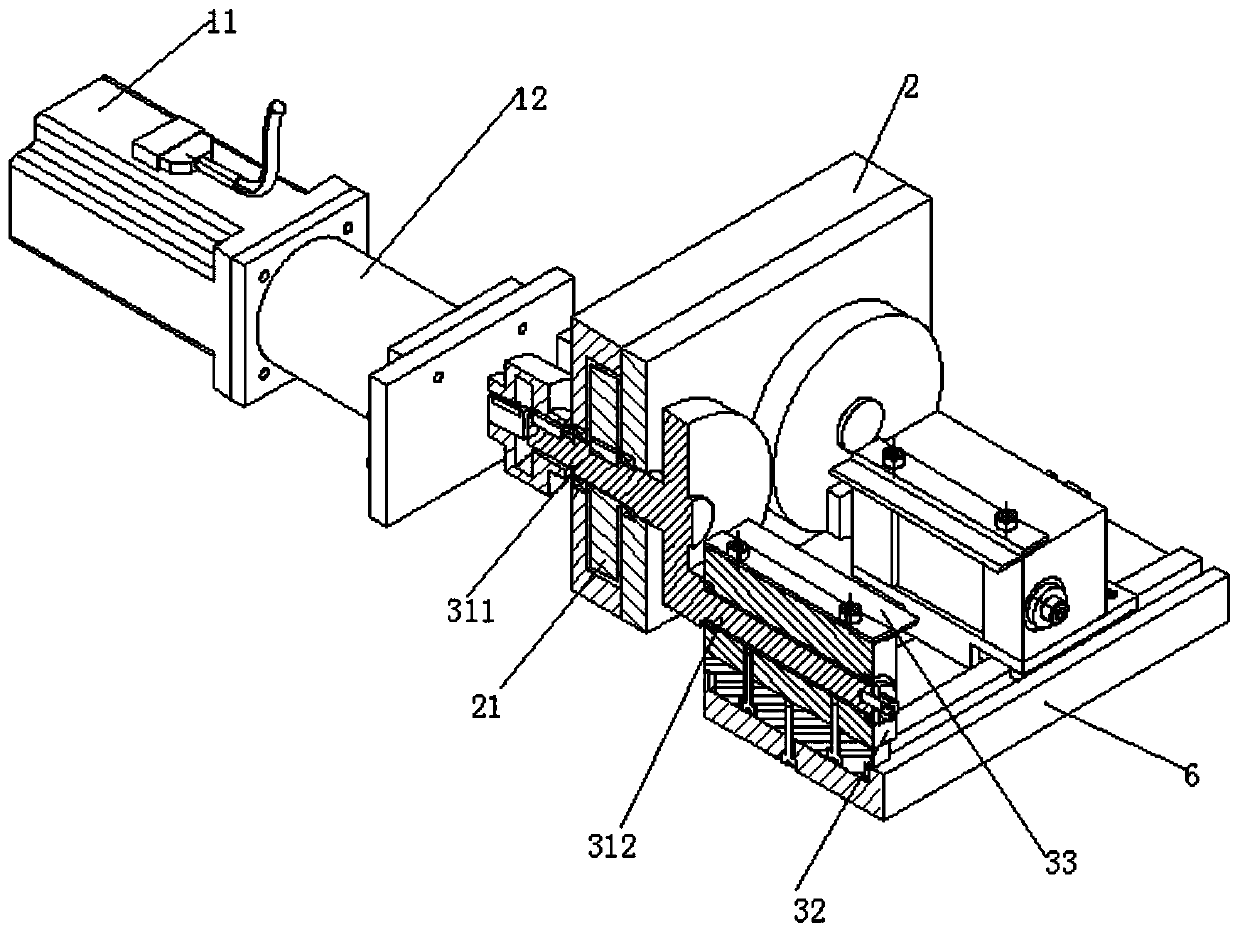
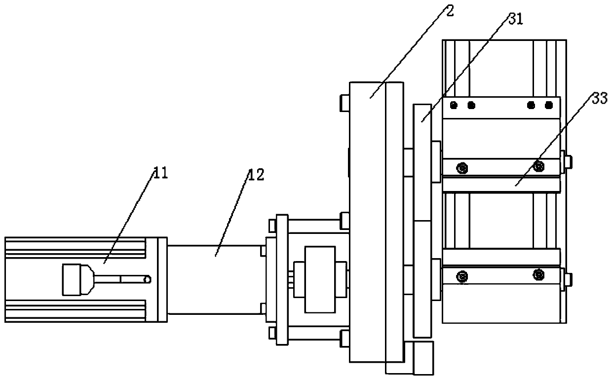
[0019] Such as Figure 1 to Figure 5 As shown, the fiber filament cutting device provided in this embodiment includes a power source, a gear box 2, a swing knife mechanism 3, a reset sensor 5 and a swing knife bottom plate 6, and the swing knife mechanism 3 has two symmetrical structures Set on the gear box 2, each knife swing mechanism 3 is made up of a swing knife wheel 31, a swing knife frame 32 and a silk cutting blade 33. The swing knife wheel 31 is formed with a rotating shaft 311 extending backward, and the swing knife The mechanism 3 is installed on the gear box 2 through the rotating shaft 311. The rotating shafts 311 of the two swinging knife mechanisms 3 are parallel to each other, and the two rotating shafts 311 are respectively corresponding to the two gears 21 meshing with each other in the gear box 2. , that is, a gear 21 is sleeved on a rotating shaft 311, and...


PUM


Abstract

The invention discloses a cellosilk cutting device. The cellosilk cutting device comprises a power source, a gear box, two pendulum tool mechanisms, a reset sensor and a pendulum tool bottom plate. Each pendulum tool mechanism is composed of a pendulum tool wheel, a pendulum tool frame and a silk cutting blade, and rotating shafts extending backward are formed on the pendulum tool wheels. The pendulum tool mechanisms are mounted on the gear box through the rotating shafts, and the rotating shafts of the two pendulum tool mechanisms correspond to two gears meshing with each other in the gear box. One of the rotating shafts extends rearward out of the gear box and is connected to the power source, and connecting rods extending forward are formed at the eccentric positions of the pendulum tool wheels. The pendulum tool frames are mounted on the connecting rods through bearings, and the silk cutting blades are horizontally mounted at the tops of the pendulum tool frames. The bottoms of thetwo pendulum tool frames are both mounted on the pendulum tool bottom plate, and the reset sensor is mounted on the gear box. The cellosilk cutting device solves the problems of striking a tool and being stuck when multiple cellosilk is transported and cut continuously at a high speed.

Description

technical field [0001] The invention relates to the technical field of chemical fiber production, in particular to a fiber cutting device. Background technique [0002] At present, the cutting devices on the market are all with one side of the cutting blade fixed, and the other cutting blade is pushed out and retracted by an air cylinder or other power to complete the cutting action. Because the fiber filaments are continuously conveyed, the two cutting blades are combined during cutting. Together, it will easily cause the fiber filaments to be stuck on the cutting blade, causing the fiber filaments to be conveyed unsmoothly, or even the fibers are directly stuck on the protruding cutting blade surface, especially when the number of fibers is large and the conveying speed is greater than 20 m / s Minutes, it can’t work directly, and the current cutting methods on the market, if the cutting speed is too fast due to the short cutting of the fiber, the above-mentioned method cann...

Claims


Application Information

Patent Timeline
Patent Type & Authority Applications(China)
IPC IPC(8): B26D7/26B26D5/00B26D5/08B26D1/25
Inventor 魏祖林
Owner ZHONGSHAN ZHENDEMEI PRECISION MASCH CO LTD
Learn More