Plate conveying device

A conveying device and plate technology, which can be used in conveyor objects, transportation and packaging, and object stacking, etc., and can solve the problems of large space and high cost.

Active Publication Date: 2019-05-24
李传聪
View PDF10 Cites 6 Cited by
  • Summary
  • Abstract
  • Description
  • Claims
  • Application Information

AI Technical Summary

Problems solved by technology

[0002] Plates are often stacked together. During processing, each plate needs to be placed in the loading area of ​​the processing equipment. The loading is often done manually; there are also large-scale loading equipment for loading, but generally speaking, the cost is high. space needs to be large

Method used


Image

  • Plate conveying device
  • Plate conveying device
  • Plate conveying device

Examples


Embodiment Construction

[0033] The technical solutions in the embodiments of the present invention will be clearly and completely described below in conjunction with the accompanying drawings in the embodiments of the present invention. Obviously, the described embodiments are only some, not all, embodiments of the present invention. Based on the embodiments of the present invention, all other embodiments obtained by persons of ordinary skill in the art without making creative efforts belong to the protection scope of the present invention.

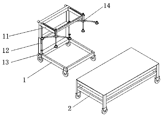
[0034] Such as figure 2 As shown, a plate conveying device includes a material transfer vehicle 1 and a loading vehicle 2; The cantilever mechanism 11 at the upper end of the vehicle frame 12, the catch mechanism 14 installed on the cantilever mechanism 11.

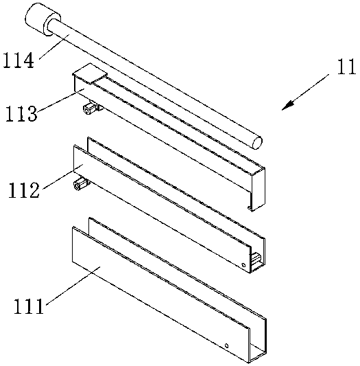
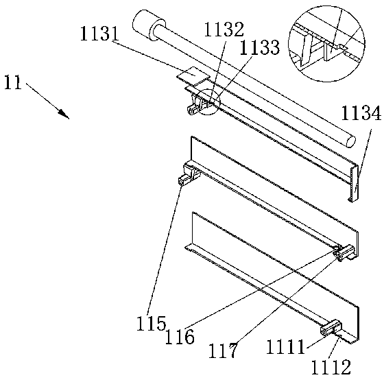
[0035] Such as image 3 , Figure 4 , Figure 5 As shown, the cantilever mechanism 11 includes a channel steel bottom cantilever 111, a middle cantilever 112 set in the bottom cantilever 111, an uppe...


PUM


Abstract

The invention discloses a plate conveying device. The plate conveying device consists of a loading car and a transfer car capable of moving; the loading car and the transfer car are locked through carbody connecting buckles; the transfer car is provided with a suspended back capable of extending, and a grabbing mechanism mounted on the suspended back; a lifting mechanism drives the suspended backand the grabbing mechanism mounted thereon to move up and down and to further grab plates; and the suspended back is unfolded to feed the plates into an equipment loading area to achieve a plate conveying function. The device is simple in structure, less in space and low in production cost.

Description

technical field [0001] The invention relates to the field of mechanical manufacturing, in particular to a plate conveying device. Background technique [0002] Plates are often stacked together. During processing, each plate needs to be placed in the loading area of ​​the processing equipment. The loading is often done manually; there are also large-scale loading equipment for loading, but generally speaking, the cost is high. The space needs to be large. Contents of the invention [0003] In order to solve the above problems, the object of the present invention is to provide a plate conveying device, which is composed of two movable loading carts and transfer carts, the loading cart and transfer cart are locked by the connecting buckle of the car body; the transfer cart There is a retractable hanging back and a grabbing mechanism installed on the hanging back. The lifting mechanism drives the hanging back and the grabbing mechanism installed on it to move up and down to ...

Claims


Application Information

Patent Timeline
Patent Type & Authority Applications(China)
IPC IPC(8): B65G47/91B65G61/00B62B3/04B62B3/00
Inventor 李传聪
Owner 李传聪
Why Eureka
Try Eureka