Peristaltic pump head

A peristaltic pump and pump cavity technology, applied in the field of peristaltic pumps, can solve problems such as dripping, poor pressure relief effect, and inability to transport liquids

Active Publication Date: 2019-05-24
重庆金山医疗技术研究院有限公司
View PDF7 Cites 4 Cited by
  • Summary
  • Abstract
  • Description
  • Claims
  • Application Information

AI Technical Summary

Problems solved by technology

[0004] Although the above-mentioned peristaltic pump can adjust the position of the positioning slider relative to the hose through the displacement adjustment mechanism, which can solve the problem of liquid dripping from the hose after the peristaltic pump stops, it still has the following problems: because the positioning slider is located on the hose and the contact surface between the positioning slider and the hose is a smooth surface. There is no limit st

Method used


Image

  • Peristaltic pump head
  • Peristaltic pump head
  • Peristaltic pump head

Examples


Example Embodiment

[0045] Example one

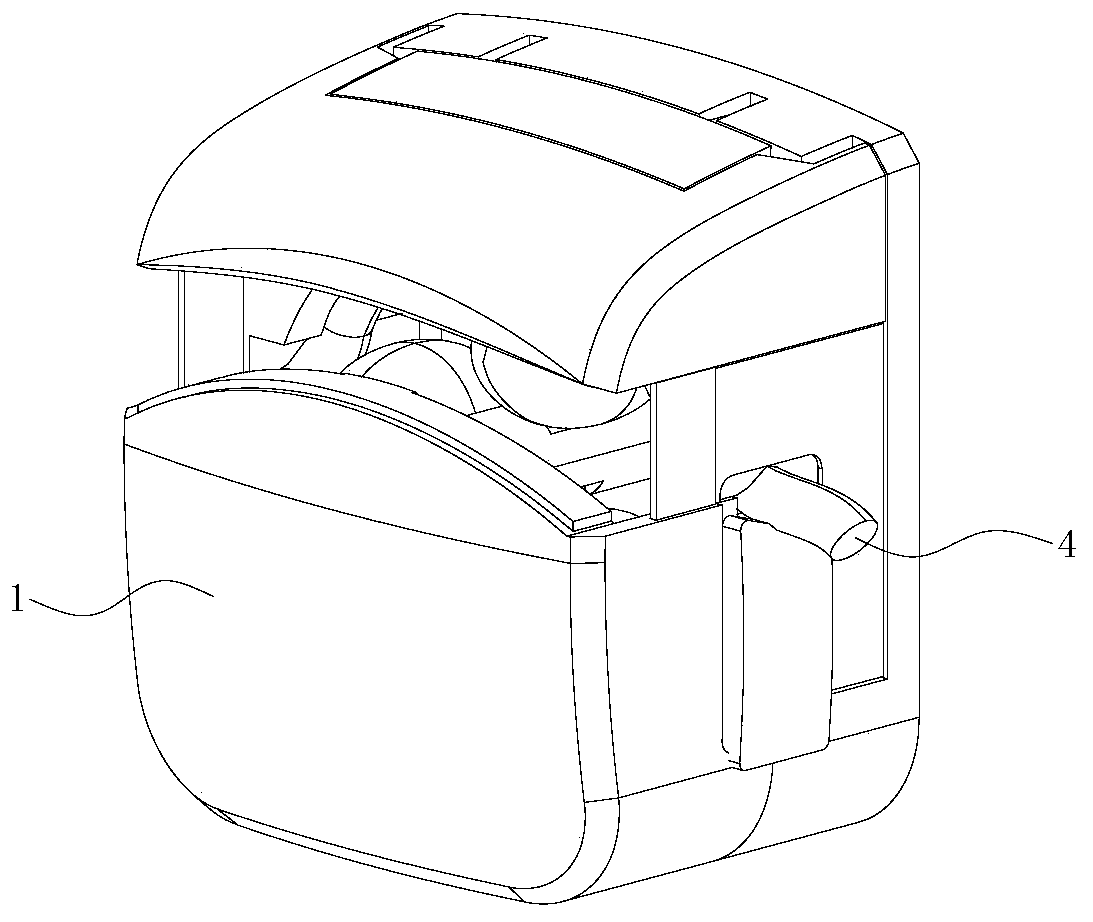
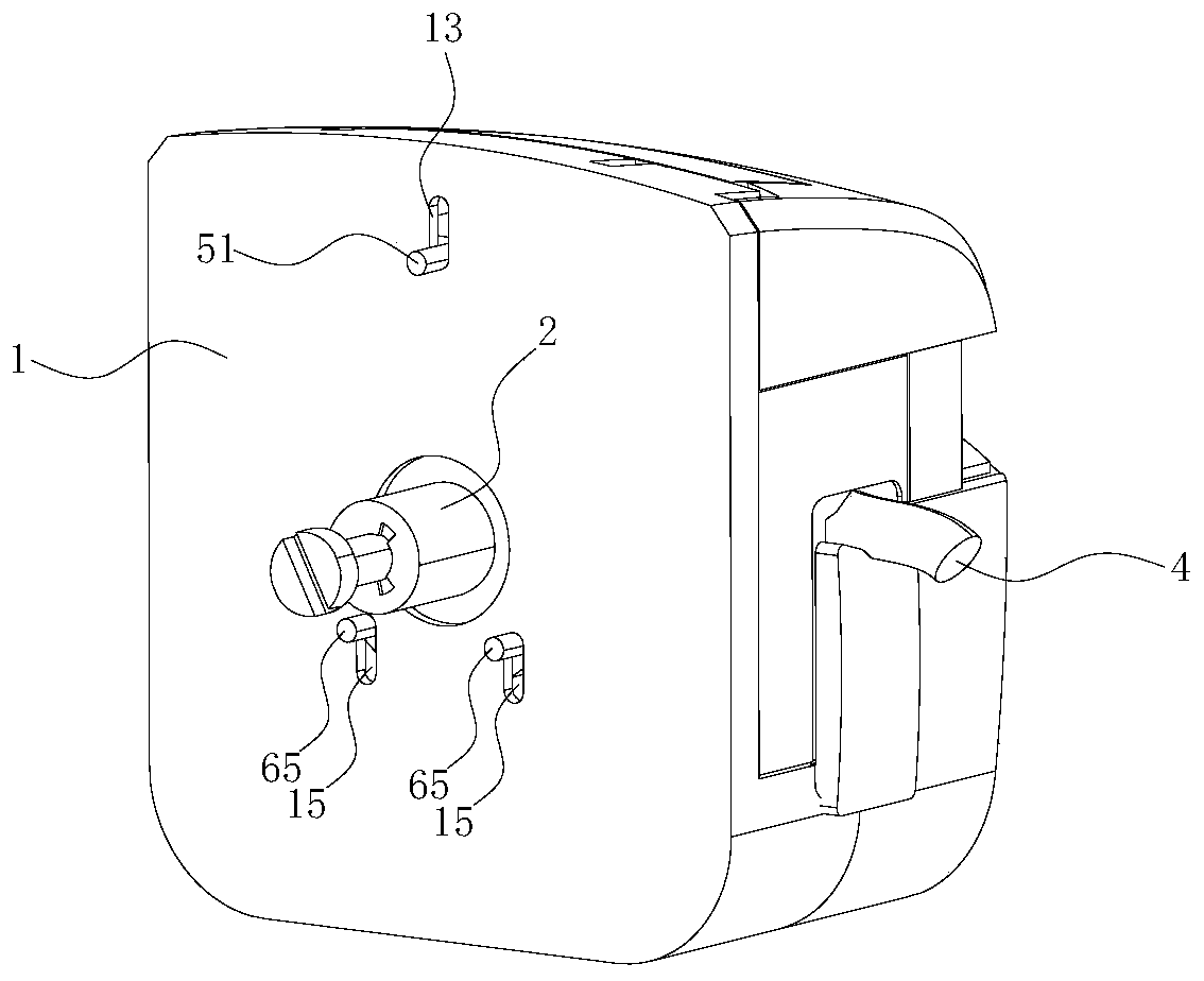
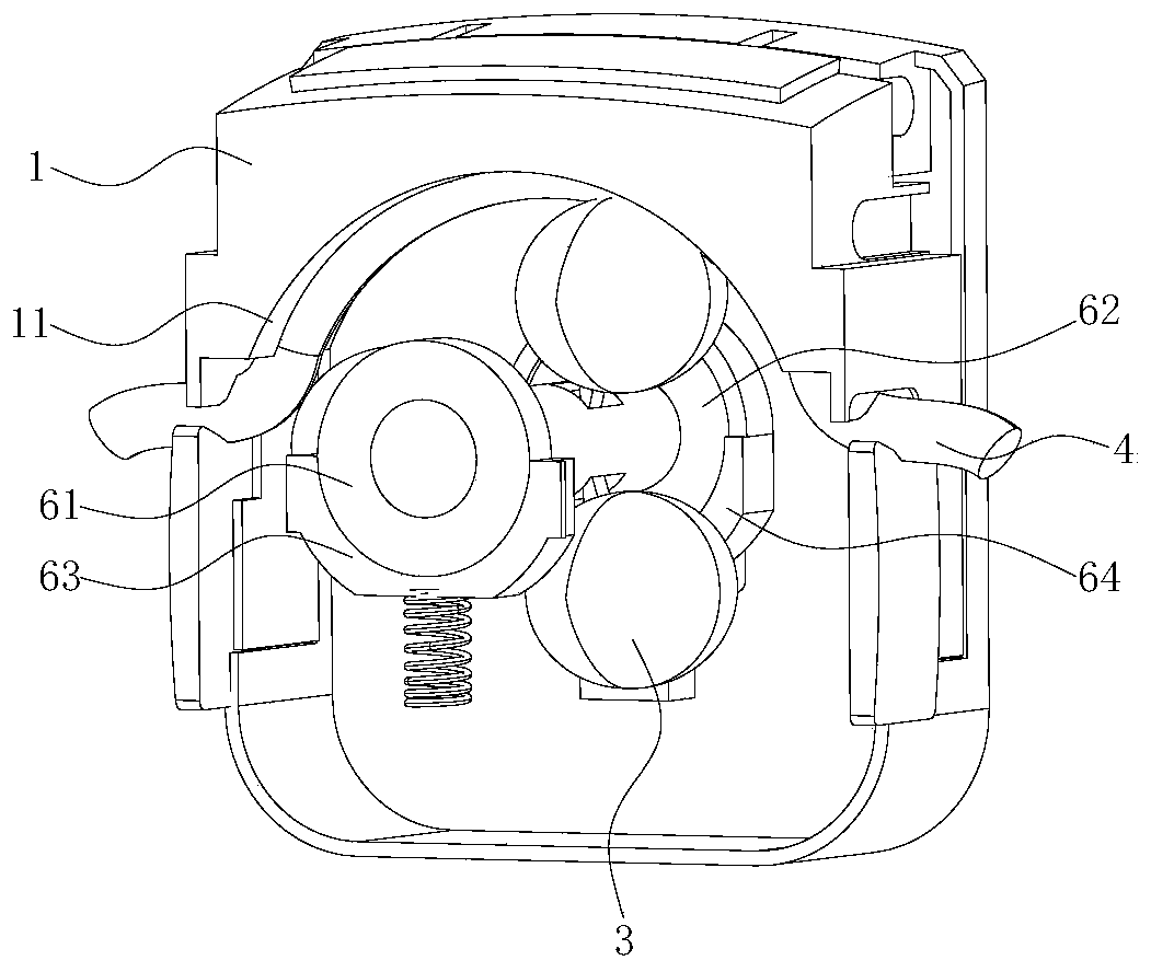
[0046] Such as figure 1 with figure 2 The shown peristaltic pump head includes a pump body 1 with a pump cavity inside and a main shaft 2 penetrating the pump cavity along the front and rear directions of the pump body 1, such as image 3 with Figure 4 As shown, the main shaft 2 is provided with three evenly distributed rollers 3, and the left and right sides of the pump cavity are respectively provided with a clamping hole. The hose 4 passes through one of the clamping holes into the pump cavity and then passes through the other clamping hole. Out, such as Figure 4 As shown, the top of the pump cavity has a cylindrical surface 11 arranged coaxially with the main shaft 2, and the hose 4 is pressed against the cylindrical surface 11 under the action of the roller 3, as Figure 5 , Image 6 , Figure 7 with Figure 8 As shown, the cylindrical surface 11 has a concave hole 12 extending radially along the main shaft 2, a first pressure relief structure is provid...

Example Embodiment

[0060] Example two

[0061] The structural principle of this embodiment is basically the same as the structural principle of the first embodiment. The difference is that the recessed hole 12 is located directly above the main shaft 2, and the top of the recessed hole 12 is provided with a through hole communicating with the outside of the pump body 1. The driving unit is a cylinder with a piston rod fixed on the upper part of the pump body 1. The piston rod of the cylinder passes through the through hole and is fixedly connected to the sliding seat 5. When the piston rod of the cylinder contracts, the sliding seat 5 is driven to move upwards to make the hose 4 Pressure relief. In this case, when the piston rod of the cylinder extends to the longest, the end surface of the sliding seat 5 near the end of the main shaft 2 is higher than the cylindrical surface 11. After the pressure is relieved, in order to enable the sliding seat 5 to be reset in time, a spring is provided on the t...

Example Embodiment

[0062] Example three

[0063] The structural principle of this embodiment is basically the same as that of the first embodiment. The difference is that the roller 3 is in the shape of a truncated cone and its central axis is parallel to the central axis of the main shaft 2, and the diameter of the roller 3 gradually decreases from front to back. When the main shaft 2 is in the working state, the roller 3 is squeezed on the hose 4 at the largest diameter. Since the diameter of the roller 3 gradually decreases from front to back, the diameter of its front end is the largest. The front end of the roller 3 is squeezed on the hose 4 when the main shaft 2 is in the working state. When the pressure needs to be relieved, the driving roller 3 moves from back to front.


PUM


Abstract

The invention provides a peristaltic pump head, belongs to the technical field of peristaltic pumps, and solves the problems that an existing peristaltic pump is bad in hose locating effect and poor in pressure relief effect. The peristaltic pump head comprises a pump body and a main shaft; the pump body is internally provided with a pump cavity; the main shaft is arranged in the pump cavity in apenetrating manner along the front-and-back direction of the pump body; a plurality of rollers annularly distributed uniformly are arranged on the main shaft; clamping holes are separately formed in the left side and the right side of the pump cavity; a hose penetrates into the pump cavity via one clamping hole and then extends out of the another clamping hole in a penetrating manner; a cylindrical surface coaxial to the main shaft is arranged at the top of the pump cavity; the hose is stuck on the cylindrical surface under the action of the rollers; a concave hole extending in the radial direction of the main shaft is formed in the cylindrical surface; a first pressure relief structure is arranged in the concave hole; and a second pressure relief structure is arranged below the hose. Theperistaltic pump head has the advantages of good pressure relief effect and good locating effect on the hose.

Description

technical field [0001] The invention belongs to the technical field of peristaltic pumps and relates to a peristaltic pump head. Background technique [0002] Peristaltic pump is a new type of fluid delivery pump after rotor pump, centrifugal pump, diaphragm pump, etc. It is being widely promoted and applied in various industries such as medical treatment, medicine, food, beverage, chemical industry, and smelting. Existing peristaltic pumps cannot immediately stop the flow of liquid when the motor stops, but will cause the problem of liquid dripping, which will bring great discomfort to doctors when used, especially when used in medical operations, and waste operations. time. [0003] For this reason, the Chinese patent discloses a multi-purpose combined peristaltic pump [the authorized announcement number is CN207634276U], which includes a lower support base, a motor, a roller, a wheel frame, a hose, a positioning slider and a displacement adjustment mechanism; The front ...

Claims


Application Information

Patent Timeline
IPC IPC(8): F04B43/12F04B53/04
Inventor 彭章杰童万里徐松张志良肖建明
Owner 重庆金山医疗技术研究院有限公司
Why Eureka
Try Eureka