
Mechanical arm end effector for leak stopping with pressure

An end effector and pressure plugging technology, which is applied in the direction of manipulators, mechanical equipment, pipes/pipe joints/pipe fittings, etc., can solve problems such as infringement, safety hazards, low efficiency, etc., and achieve the effect of improving accuracy

Active Publication Date: 2019-05-24
HUANENG SHANTOU HAIMEN POWER GENERATION CO LTD +1
View PDF3 Cites 6 Cited by
  • Summary
  • Abstract
  • Description
  • Claims
  • Application Information

AI Technical Summary

Problems solved by technology

For the leakage of pipelines and containers in the production process of the enterprise, the existing leakage defects are manually plugged, and the efficiency is low, and the high temperature, high pressure, corrosive and odorous leakage will cause certain damage to the plugging operators. Safety hazards and physical assault

Method used


Image

  • Mechanical arm end effector for leak stopping with pressure
  • Mechanical arm end effector for leak stopping with pressure
  • Mechanical arm end effector for leak stopping with pressure

Examples


Embodiment Construction

[0019] In order to facilitate the understanding of the present invention, the present invention will be described more fully below with reference to the associated drawings. A preferred embodiment of the invention is shown in the drawings. However, the present invention can be embodied in many different forms and is not limited to the embodiments described herein. Rather, these embodiments are provided so that the disclosure of the present invention will be thorough and complete.

[0020] It should be noted that when an element is referred to as being “fixed on” another element, it may be directly on the other element or there may be an intervening element. When an element is referred to as being "connected to" another element, it can be directly connected to the other element or intervening elements may also be present. The terms "vertical," "horizontal," "left," "right," and similar expressions are used herein for purposes of illustration only.

[0021] Unless otherwise d...


PUM


Abstract

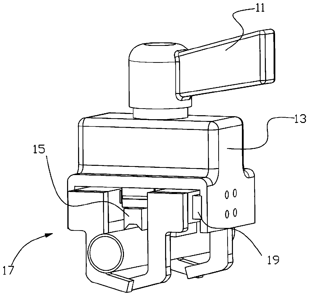
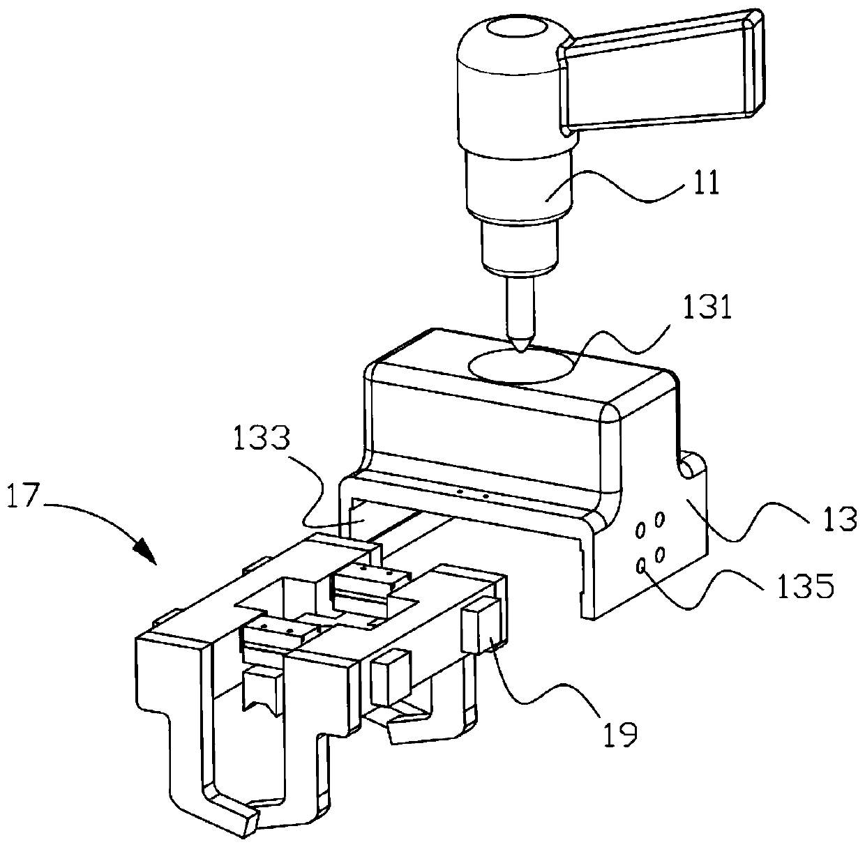
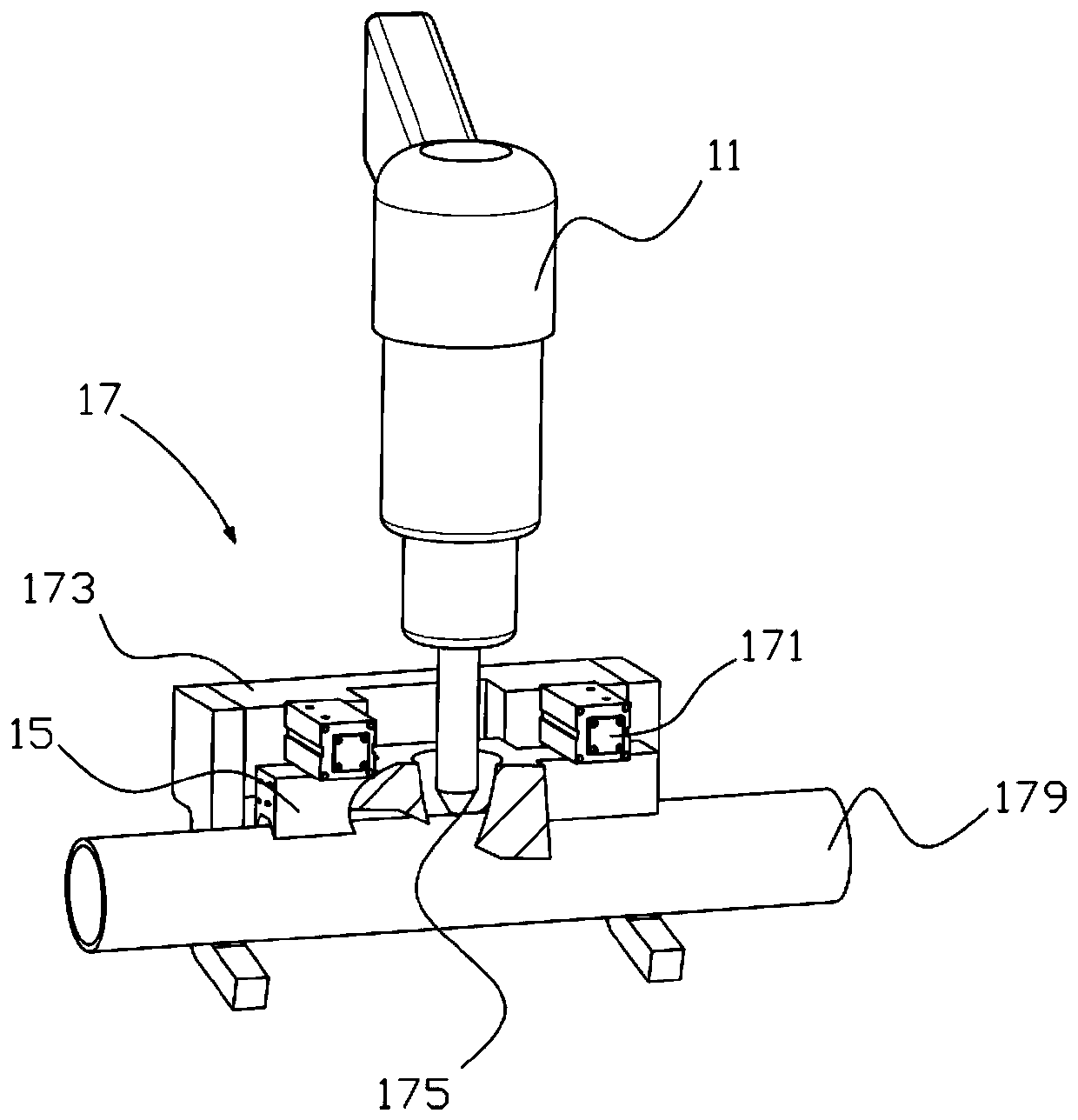
The embodiment of the invention discloses a mechanical arm end effector for leak stopping with pressure. The mechanical arm end effector comprises an air impact hammer, a raised block, connecting blocks, a V-shaped self-centering module, and a clamping module. The clamping module is composed of air cylinders and two clamping jaws, the air cylinders are installed between the two clamping jaws, eachof the clamping jaws consists of a depressed block and two L-shaped plates, the connecting blocks are fixedly arranged on the outer sides of the two clamping jaws, the clamping module is installed atthe two ends of the raised block through the connecting blocks, the V-shaped self-centering module is fixedly arranged under the air cylinders, the air impact hammer is fixedly arranged on the raisedpart of the upper end of the raised block and penetrates through the V-shaped self-centering module, and leak points on leaked equipment are subjected to beating and striking and leak stopping. The mechanical arm end effector is novel in structural design and convenient to operate and can be applied to the beating and striking and leak stopping of various-sized leaked pipelines, self-centering can be realized by the V-shaped self-centering module, and leak stopping accuracy is high.

Description

technical field [0001] The present invention relates to a leak plugging device under pressure, in particular to a mechanical arm end effector for leak plugging under pressure. Background technique [0002] Leakage plugging under pressure refers to any pressure pipes and tanks with pressure above one atmosphere to store or transport medium due to corrosion, perforation, leaking, dripping, leaking or man-made damage. Methods. Mainly for oil, oil refining, ethylene, chlor-alkali, gas, chemical industry, power plants, paper mills, ships, properties and households and other types of pipelines and tanks corrosion perforation leakage leakage. Nowadays, the pressure plugging technology has been widely used in electric power and chemical enterprises, and has become an important means for enterprises to achieve long-term and no leakage. At the same time, avoiding the discharge of materials caused by parking not only brings huge economic benefits to enterprises, but also has great env...

Claims


Application Information

Patent Timeline
Patent Type & Authority Applications(China)
IPC IPC(8): F16L55/168B25J15/00
Inventor 陈伟武孙伟鹏白玉峰范衠陈锦华林楚伟江永朱贵杰游煜根陈文钊唐紫樑万琪
Owner HUANENG SHANTOU HAIMEN POWER GENERATION CO LTD
Learn More