
Shock tunnel explosion relief device with continuously and uniformly adjustable explosive relief efficacy

A technology of shock tunnel and throttling device, which is applied to measuring devices, testing of machine/structural components, instruments, etc., can solve the problems of high test cost, unrealistic, troublesome replacement process, etc., and achieves uniform and continuous adjustment process. The effect of improving experimental efficiency and reducing the cost of experimental equipment

Inactive Publication Date: 2019-05-24
CHONGQING JIAOTONG UNIVERSITY
View PDF6 Cites 4 Cited by
  • Summary
  • Abstract
  • Description
  • Claims
  • Application Information

AI Technical Summary

Problems solved by technology

There is a common problem in the above two methods: it is impossible to achieve continuous and uniform adjustment of detonation efficiency
It is unrealistic to purchase or process thick plates or Laval nozzles of different specifications during the test, and the cost of the test increases sharply. At the same time, the replacement process is troublesome, and the continuous detonation performance cannot be achieved by changing different thick plates or Laval nozzles. adjustment, not to mention continuous and uniform adjustment

Method used


Image

  • Shock tunnel explosion relief device with continuously and uniformly adjustable explosive relief efficacy
  • Shock tunnel explosion relief device with continuously and uniformly adjustable explosive relief efficacy
  • Shock tunnel explosion relief device with continuously and uniformly adjustable explosive relief efficacy

Examples


Embodiment Construction

[0025] Embodiments of the present invention are described below through specific examples, and those skilled in the art can easily understand other advantages and effects of the present invention from the content disclosed in this specification. The present invention can also be implemented or applied through other different specific implementation modes, and various modifications or changes can be made to the details in this specification based on different viewpoints and applications without departing from the spirit of the present invention. It should be noted that, in the case of no conflict, the following embodiments and features in the embodiments can be combined with each other.

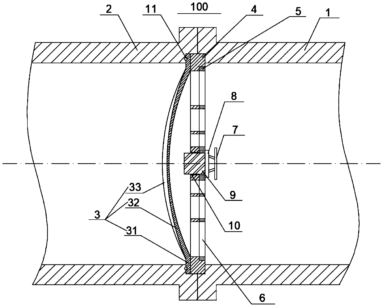
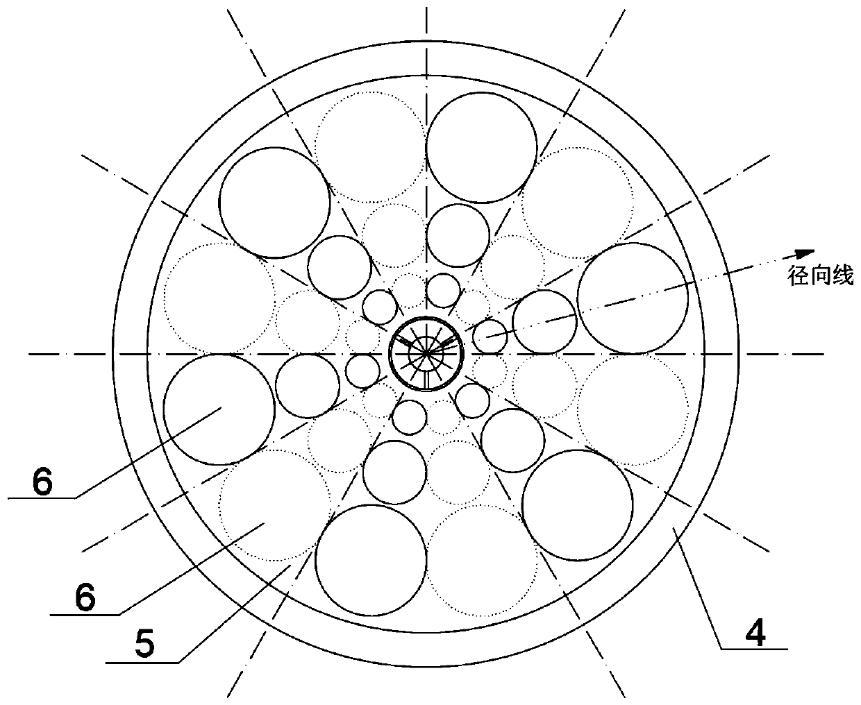
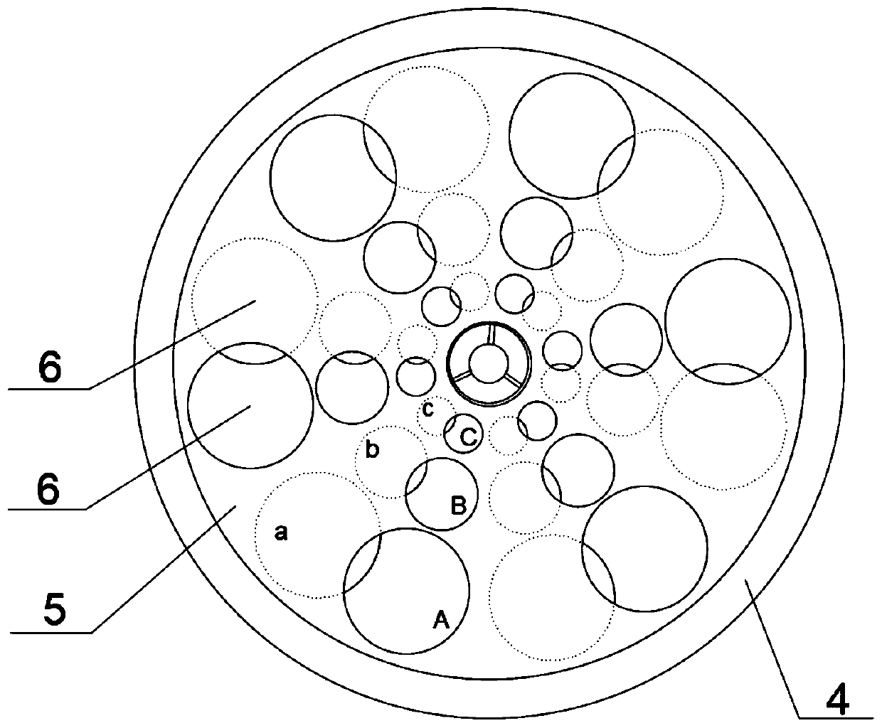
[0026] Such as figure 1 , a shock tunnel detonation device that can continuously and uniformly adjust the detonation performance, including a shock tunnel 100; the shock tunnel 100 includes a detonation drive section 1 and a detonation section 2, in the detonation drive section 1 and the deto...


PUM


Abstract

The invention provides a shock tunnel explosion relief device with continuously and uniformly adjustable explosive relief efficacy and applies to the field of wind tunnel experimental equipment. The shock tunnel explosion relief device comprises a shock wind tunnel which includes a detonation driving segment and an explosion relief segment; an explosion relief throttle device is mounted between the detonation driving segment and the explosion relief segment; the side of the explosion relief throttle device close to the explosion relief segment is provided with a diaphragm; the explosion reliefthrottle device includes a fixed plate and a moving plate attached to each other in concentric manner and having certain thickness; the moving plate can rotate around a co-axis to the moving plate and the fixed plate, and may be locked and attached to the side of the fixed plate close to the detonation driving segment under the action of a compression mechanism; the fixed plate and the moving plate are axially provided with a plurality of through holes identical in position. The explosion relief efficacy of a shock wind tunnel explosion relief segment can be autonomously adjusted as experiments require just through the single shock tunnel explosion relief device; the adjusting process is uniform and continuous; experimental equipment cost can be reduced; the explosion relief throttle device is applicable to different explosion relief experimental environments, and experimental efficiency is improved.

Description

technical field [0001] The invention relates to the field of wind tunnel experimental devices, in particular to a shock wave wind tunnel detonation device capable of continuously and uniformly adjusting the detonation efficiency. Background technique [0002] During the development of a hypersonic vehicle, a large number of ground simulation experiments are required to obtain data on the aerodynamic force and propulsion performance of the vehicle. The pulse-type shock tunnel is a kind of experimental equipment that uses unsteady shock wave compression to generate high-temperature and high-pressure gas, and plays an important role in hypersonic flow simulation. Among them, the detonation-driven shock tunnel is a way to generate unsteady shock waves by using combustible gas detonation, which has the characteristics of low operating costs. [0003] During the operation of the detonation-driven shock tunnel, the gas detonation produces a strong shock wave, which will seriously ...

Claims


Application Information

Patent Timeline
IPC IPC(8): G01M9/04
Inventor 王旭郭运刘海明
Owner CHONGQING JIAOTONG UNIVERSITY
Learn More