A wall-mounted optical fiber distribution box with cable management structure

A cable management structure and wall-mounted technology, applied in the direction of fiber mechanical structure, etc., can solve the problems of secondary damage to optical cables, affect the service life of optical cables, increase maintenance costs, etc., and achieve the effect of preventing damage

Active Publication Date: 2020-09-15
杭州奥克光电设备有限公司
View PDF12 Cites 0 Cited by
  • Summary
  • Abstract
  • Description
  • Claims
  • Application Information

AI Technical Summary

Problems solved by technology

[0004] The purpose of the present invention is to provide a wall-mounted optical cable distribution box with a cable management structure to solve the problem that the optical fiber will be deformed after being fixed for a period of time due to the lack of a special cable management structure after the optical cable is fixed into the optical fiber box. When inspection and maintenance are required, it is easy to cause secondary damage to the optical cable during the cable management process, which affects the service life of the optical cable and increases the technical problem of maintenance costs.

Method used


Image

  • A wall-mounted optical fiber distribution box with cable management structure
  • A wall-mounted optical fiber distribution box with cable management structure
  • A wall-mounted optical fiber distribution box with cable management structure

Examples


Embodiment Construction

[0035] The technical solutions of the present invention will be clearly and completely described below in conjunction with the embodiments. Apparently, the described embodiments are only some of the embodiments of the present invention, not all of them. Based on the embodiments of the present invention, all other embodiments obtained by persons of ordinary skill in the art without creative efforts fall within the protection scope of the present invention.

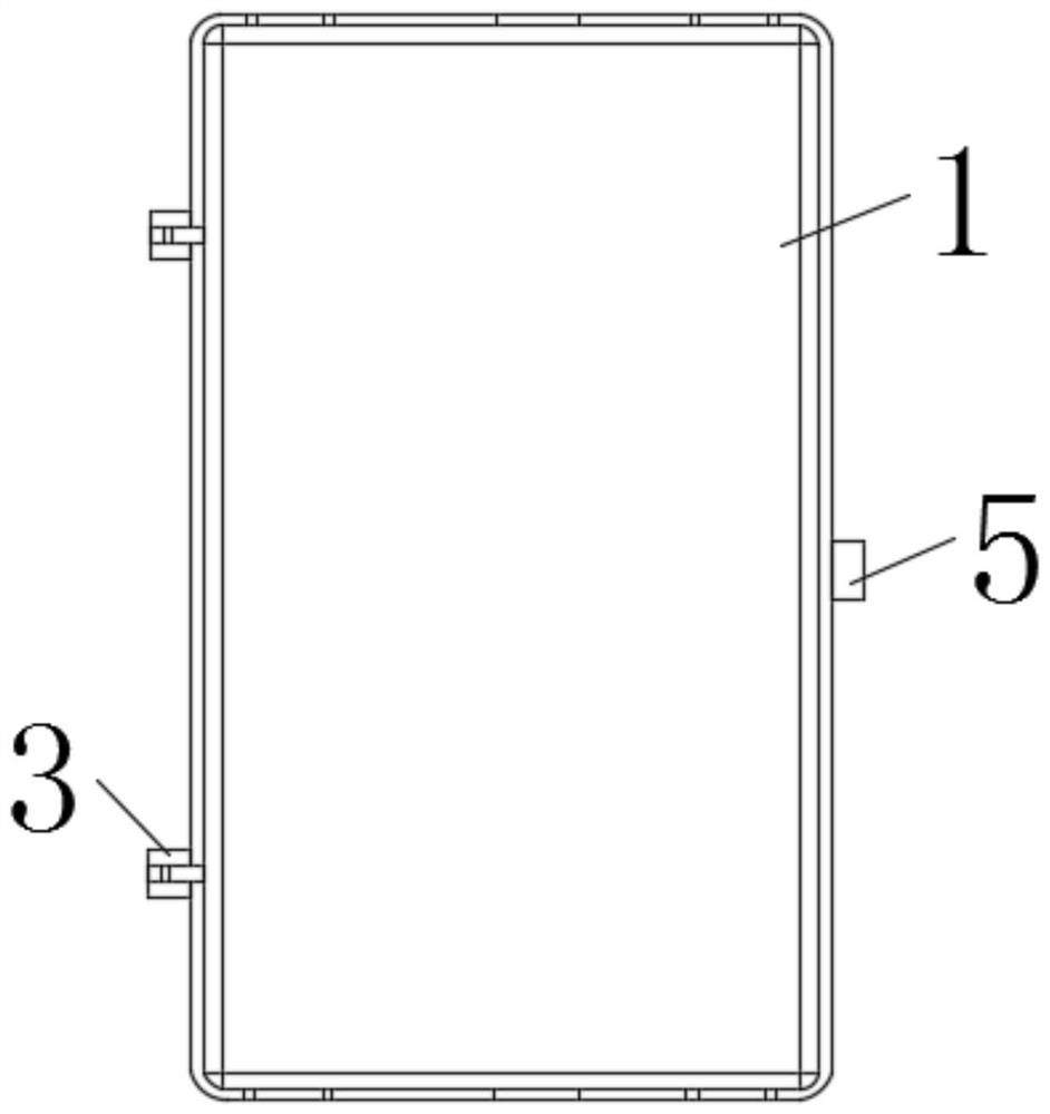
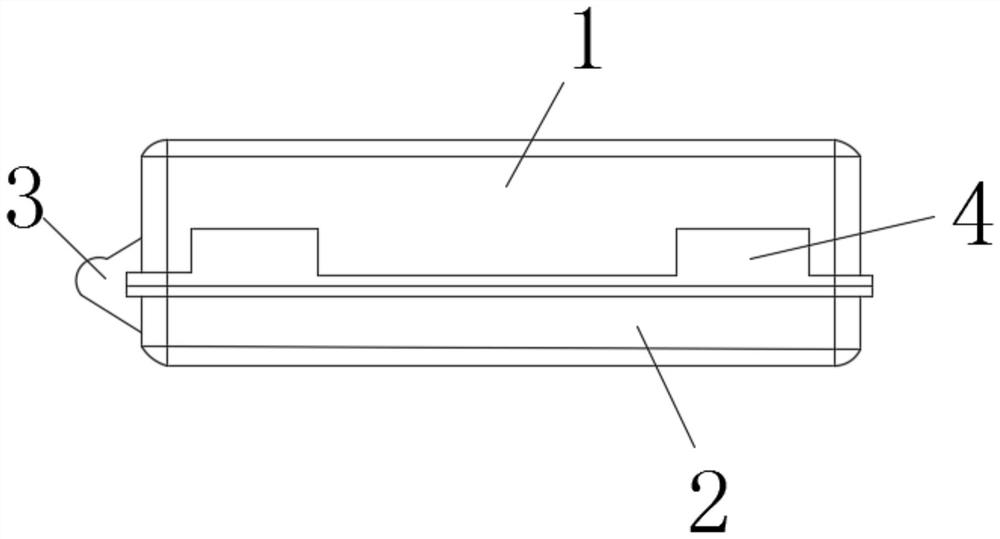
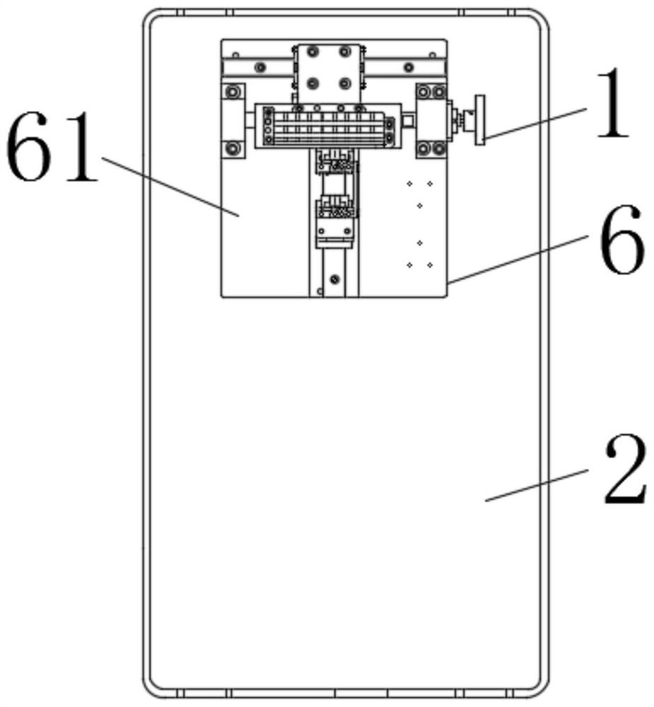
[0036] See Figure 1-8 , a wall-mounted fiber optic cable distribution box with a cable management structure, including an upper housing 1, a lower housing 2, a connector 3, a lead hole 4, a bump 5 and a cable management mechanism 6, wherein the upper housing 1 and the The lower shells 2 are movably connected by the connecting piece 3, and the connecting piece 3 can make the upper shell 1 and the lower shell 2 be in a sealed or open state. The bottom end of the upper shell 1 is provided with a lead hole 4, and the lead wire...


PUM


Abstract

The invention discloses a wall-mounted optical fiber cable distribution box with a wire trimming structure. The wall-mounted optical fiber cable distribution box comprises an upper shell, a lower shell, a connector, a wire hole, a convex block and the wire trimming structure, a second fixed plate is horizontally fixed to the top end of a third fixing base in a welded manner, clamping blocks are fixedly connected with movable blocks through bolts, the movable blocks are mounted in the second fixed plate, the two clamping blocks are oppositely arranged, stoppers are mounted on the outer sides ofthe two movable blocks through bolts, a first pin is twisted, so that the gap between the two clamping blocks is enlarged, an optical cable penetrates the space between the two clamping blocks, the first pin is twisted again, the optical cable is fixed between the clamping blocks and can slide relative to the clamping blocks without slip after being stressed, the optical cable penetrates a groovein a second fixing base and can be limited in the second fixing base by a retainer wheel, and the optical cable cannot be staggered with other optical cables in the wire trimming process and prevented from damaging the other optical cables when needing maintenance and wire trimming.

Description

technical field [0001] The invention relates to an optical cable fiber distribution box, in particular to a wall-mounted optical cable fiber distribution box with a cable management structure, and belongs to the technical field of application of the wall-mounted optical cable fiber distribution box. Background technique [0002] Optical cables are manufactured to meet optical, mechanical or environmental performance specifications. It is a communication cable assembly that uses one or more optical fibers placed in a sheath as a transmission medium and can be used individually or in groups. The optical cable is mainly composed of optical fiber (glass filament as thin as hair), plastic protective sleeve and plastic sheath. There is no metal such as gold, silver, copper and aluminum in the optical cable, and generally has no recycling value. An optical cable is a communication line in which a certain number of optical fibers form a cable core in a certain way, and is covered wi...

Claims


Application Information

Patent Timeline
Patent Type & Authority Patents(China)
IPC IPC(8): G02B6/44
Inventor 金辉
Owner 杭州奥克光电设备有限公司
Why Eureka
Try Eureka