Textile Machine Warp Roller Winding Guide Mechanism

A technology of warp rollers and textile machines, which is applied in thin material processing, delivery of filamentous materials, transportation and packaging, etc. It can solve the problems of cumbersome operation and difficulty in uniform warp roller surface size, and achieve the effect of uniform arrangement

Active Publication Date: 2022-05-17
岳西神农氏农业科技有限公司
View PDF15 Cites 0 Cited by
  • Summary
  • Abstract
  • Description
  • Claims
  • Application Information

AI Technical Summary

Problems solved by technology

In the prior art, in order to overcome this technical problem, the liner is generally wrapped on the warp roll to keep the outer surface of the warp roll as smooth as possible. However, this operation method is cumbersome to operate on the one hand, and it is difficult to ensure the smoothness of the warp roll on the other hand. Uniform surface size

Method used


Image

  • Textile Machine Warp Roller Winding Guide Mechanism
  • Textile Machine Warp Roller Winding Guide Mechanism
  • Textile Machine Warp Roller Winding Guide Mechanism

Examples


Embodiment 1

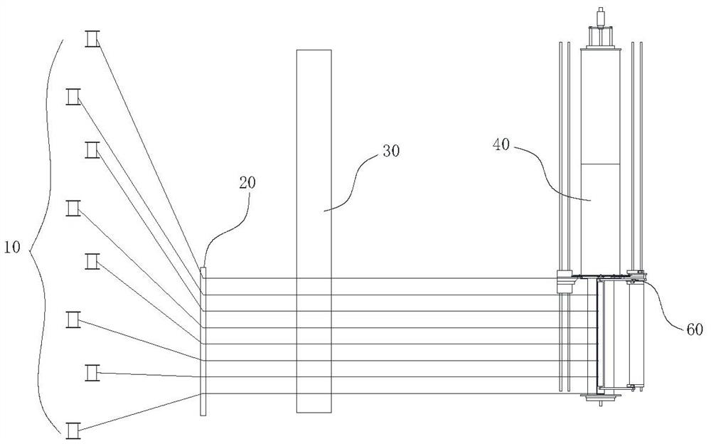
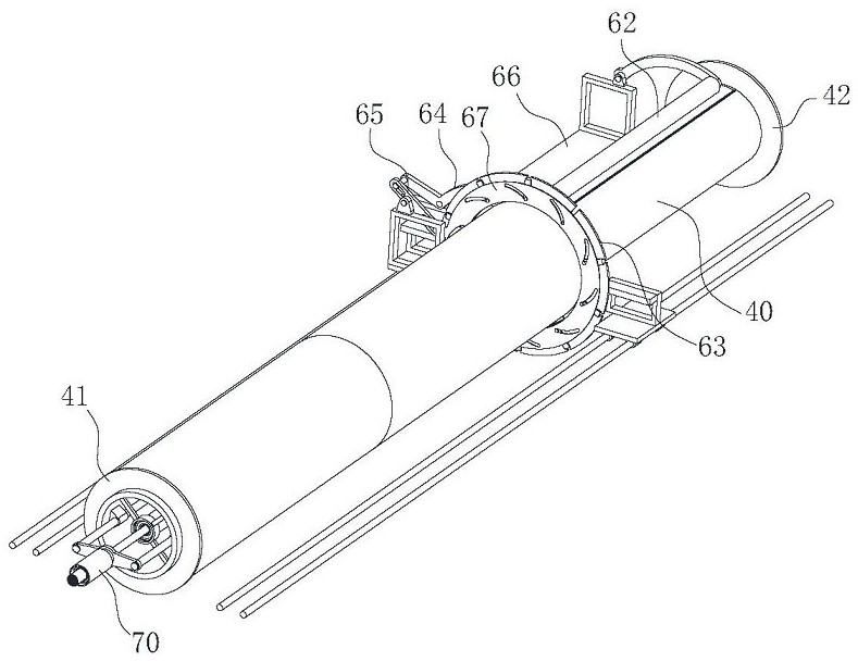
[0033] a textile machine, such as figure 1 As shown, it includes a warp roller winding mechanism, and the warp winding mechanism includes a warp roller, a guide plate 20, a pay-off roller 10 and a shaping roller 30, and the pay-off roller 10 is arranged on a pay-off rack in a plurality of arrays, The thread ends on each pay-off roller 10 are drawn in the same direction, and each thread end passes through the threading holes 21 arranged in an array on the guide plate 20 respectively, and is finally wound on the warp roller; the shaping roller 30 tensions the thread between the warp roller and the guide plate 20 and arranges the threads at equal intervals; the warp roller includes an outer roller 40 and an inner roller 50 that are coaxially rotatably connected, and the inner roller 50 is located at Inside the outer roller 40, the roller surface of the outer roller 40 is provided with a bar hole 401 penetrating the wall of the outer roller 40 along the direction of the generatrix...

Embodiment 2

[0044]A kind of textile machine warp thread winding method described in embodiment 1, comprises the steps:

[0045] Step 1: Set the warp roller;

[0046] Step 2: Pulling the wires, laying out the array of pay-off rollers 10 on the pay-off frame, moving the end of the thread on each pay-off roller 10 out and passing through the threading holes 21 set on the guide plate 20;

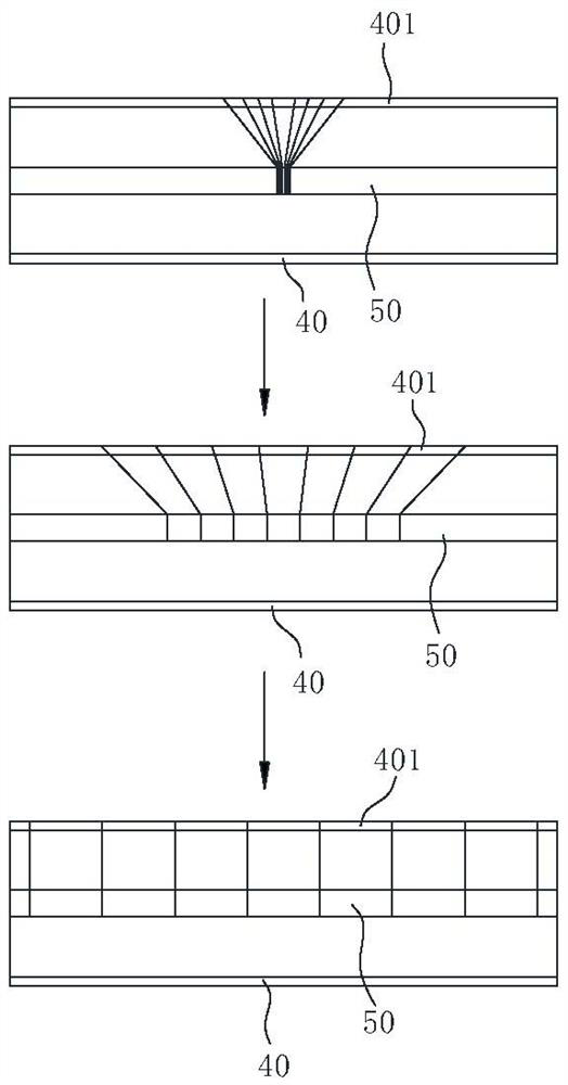
[0047] Step 3: Bundle the wire ends into a bundle and fix it at the center position of the first inner roller 50, and spread the wire between the inner roller 50 and the guide plate 20 on the shaping roller 30;

[0048] Step 4: Rotate the first inner roller 50 and keep the outer roller 40 still, so that each thread gradually spreads from the center of the first inner roller 50 to both ends;

[0049] Step 5: Start the outer roller 40 when the silk thread covers the entire roller surface of the first inner roller 50, and make the outer roller 40 and the first inner roller 50 rotate synchronously, so that the...


PUM


Abstract

The invention belongs to the technical field of silk processing and textile, and specifically relates to a warp roller winding guide mechanism of a textile machine, comprising an outer roller, one end of the outer roller is fixedly provided with a first baffle plate, and the roller surface of the outer roller A second baffle plate sliding along the axial direction of the outer roller is provided on the top; an expansion and contraction protection mechanism is also provided between the first baffle plate and the second baffle plate. The invented second baffle can protect the end surface of the wire coil on the side away from the first baffle during the winding process, so that the end surface of the wire coil can be kept flat, so as to ensure that there will be no collision with the wire in this section when the next section is wound. Staggered; in addition, the expansion and contraction protection mechanism can support the end surface of the upper section of the wire to prevent the end surface from collapsing due to the high-speed rotation of the wire roller, and the expansion and contraction protection mechanism can keep away from the winding of the section of the wire The roller surface of the outer roller makes the wire coils in two adjacent sections closely contact, thereby ensuring that the bottom threads on the entire warp roller are closely and evenly arranged.

Description

technical field [0001] The invention belongs to the technical field of silk processing and textile, and in particular relates to a warp roller winding guide mechanism of a textile machine. Background technique [0002] The warp of the textile machine refers to the thread parallel to the overall discharge direction of the textile fabric, and the warp and weft are vertically interwoven to form the fabric. Before the textile machine starts to work, it is necessary to wind multiple strands of warp on the warp roller, and the warp roller will pay out at a constant speed as the weaving progresses. Local relaxation occurs. However, when the warp roll is winding the warp thread, thousands of silk threads are first divided into several groups, and about several hundred silk threads in each group are bundled into a bundle, and then fixed on the warp thread roll, so that multiple warp threads will appear on the inverted warp thread roll. Bulges, these bulges will make the winding and...

Claims


Application Information

Patent Timeline
Patent Type & Authority Patents(China)
IPC IPC(8): B65H57/06B65H51/06B65H51/005B65H51/015B65H75/24B65H75/18B65H49/32B65H59/10B65H54/54B65H54/70B65H54/28
CPCB65H57/06B65H51/06B65H51/005B65H51/015B65H75/242B65H75/18B65H49/32B65H59/10B65H54/54B65H54/70B65H54/28B65H2701/31
Inventor 金绿英
Owner 岳西神农氏农业科技有限公司
Why Eureka
Try Eureka