Display substrate, display panel and display device

A technology for display substrates and display panels, which is applied in plane/plate-shaped light guides, instruments, optics, etc., can solve problems such as poor color crossover, and achieve the effect of small deflection angle, solving color crosstalk problems, and small light exit angle.

Inactive Publication Date: 2019-05-24
BOE TECH GRP CO LTD
View PDF6 Cites 9 Cited by
  • Summary
  • Abstract
  • Description
  • Claims
  • Application Information

AI Technical Summary

Problems solved by technology

[0004] The present invention provides a display substrate, a display panel and a display device, which are used to solve the problem that liquid crystal display devices are prone to poor color crossover when using collimated light source display technology

Method used


Image

  • Display substrate, display panel and display device
  • Display substrate, display panel and display device
  • Display substrate, display panel and display device

Examples


Embodiment Construction

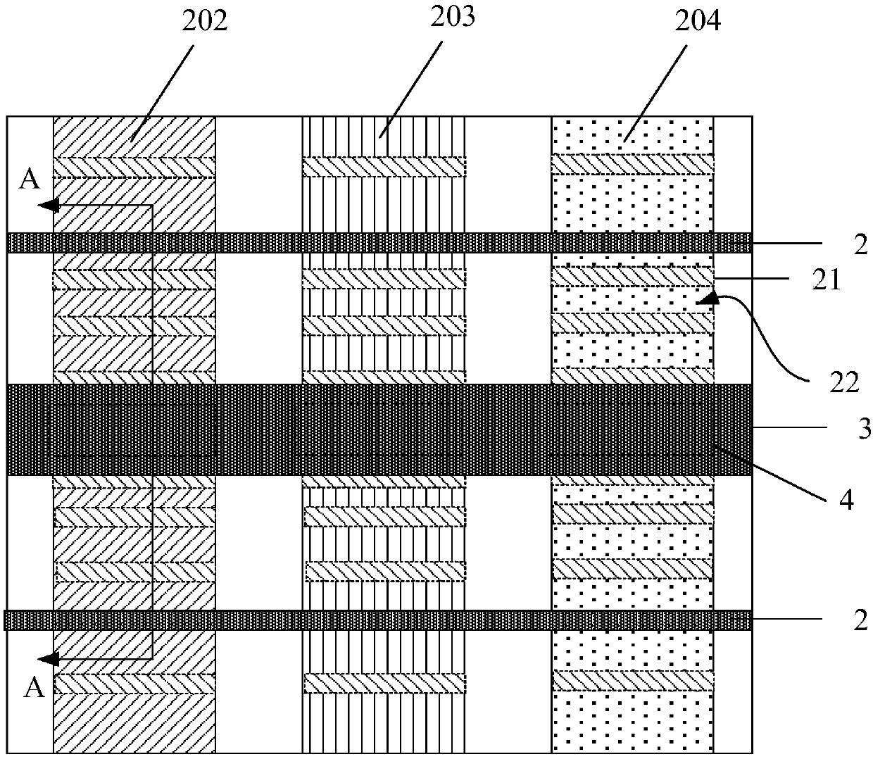
[0031] For a horizontal electric field type liquid crystal display device using a collimated light source (hereinafter referred to as a collimated light source liquid crystal display device), its pixel electrodes and common electrodes are both arranged on the array substrate, and the pixel electrodes and / or common electrodes are slit electrodes for A horizontal driving electric field is formed to drive liquid crystal molecules to deflect and control the display process. Wherein, the slit electrode is composed of multiple sub-electrodes, and there are slits between adjacent sub-electrodes. The slits of the existing slit electrodes are designed to be equal in width. Although the light emitting angle can be ensured, color crossing defects are prone to occur. This is the technical problem to be solved by the present invention.

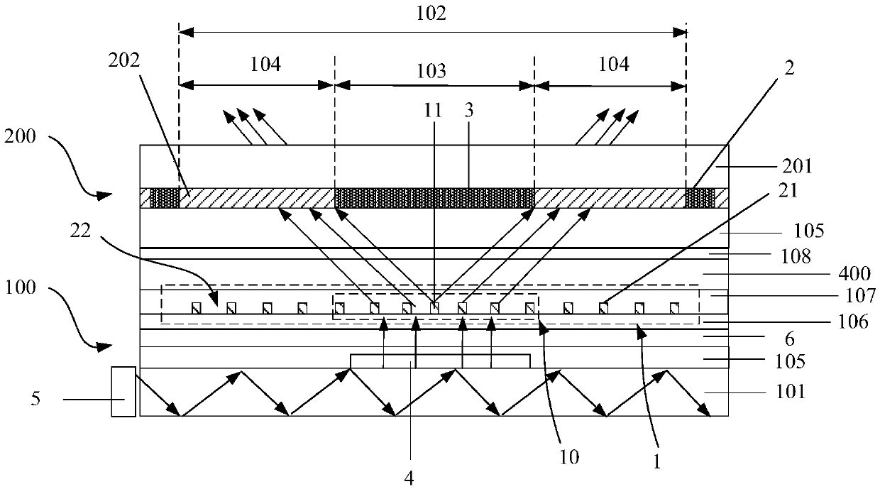
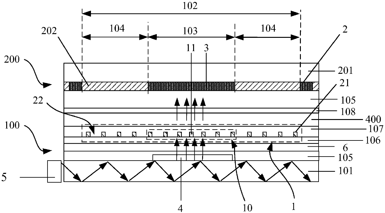
[0032] Before describing the technical solution of the present invention, first briefly introduce the main structure and working principle of the liquid c...


PUM


Abstract

The invention provides a display substrate, a display panel and a display device. The display substrate includes a plurality of sub-pixel areas. Each sub-pixel area includes a shading area and openingareas on the two sides. A first transparent electrode is arranged in each sub-pixel area. Each first transparent electrode includes a first electrode unit located in the corresponding shading area. Each first electrode unit includes a plurality of first sub-electrodes. A first slit is arranged between the adjacent first sub-electrodes. The width of the first slits progressively increases in a direction from the centers of the shading areas to the sides where the shading areas and the opening areas are connected to each other. Liquid crystals corresponding to the small slits at the central areas of the shading areas can form large liquid crystal prism curvature, has large deflection angles to light and large light-emitting angles, and ensures light-emitting efficiency. Liquid crystals corresponding to the wide slits at the edge areas can form small liquid crystal prism curvature, has small deflection angles to light and small light-emitting angles, and ensures that the light does not be emitted out of the adjacent sub-pixel areas. The display substrate, the display panel and the display device solve the problem of cross-color.

Description

technical field [0001] The present invention relates to the field of display technology, in particular to a display substrate, a display panel and a display device. Background technique [0002] For a transverse electric field liquid crystal display device, the light emitted by the backlight needs to pass through two layers of polarizers, which has low transmittance and high power consumption. In order to solve the above-mentioned technical problems, the collimated light source display technology is adopted in the prior art. The collimated light source display technology projects the collimated light to the liquid crystal layer through the light-taking port, and the position of the light-taking port is correspondingly provided with a light-shielding pattern. When the driving electric field is not applied, the collimated light at the light-taking port is blocked by the light-shielding pattern to realize the dark state display. When the driving electric field is applied, the ...

Claims


Application Information

Patent Timeline
Patent Type & Authority Applications(China)
IPC IPC(8): G02F1/1343
CPCG02F2201/30G02F2203/30G02F2201/128G02F1/133615G02F1/133512G02F1/29G02F1/134309G02F2203/62G02F1/133526G02B6/005G02F1/134372G02F1/291G02F1/133567G02F1/134345G02F1/133514G02F1/133524G02F1/134363G02F1/13439G02F1/1393
Inventor 赵德涛肖丽王磊刘冬妮陈亮谭纪风玄明花陈小川
Owner BOE TECH GRP CO LTD
Why Eureka
Try Eureka