Optical lens, camera module, electronic equipment and automobile
A technology of optical lens and camera module, which is applied in optics, optical components, instruments, etc., can solve the problems of small monitoring area and small field of view, and achieve the goal of reducing field curvature, large field of view, and reducing edge aberration Effect
- Summary
- Abstract
- Description
- Claims
- Application Information
AI Technical Summary
Problems solved by technology
Method used
Image
Examples
no. 1 example
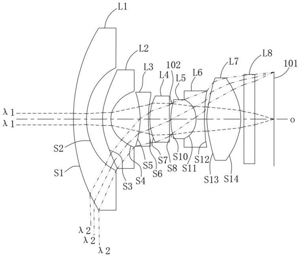
[0076] Such as figure 1 As shown, the optical lens 100 includes a first lens L1, a second lens L2, a third lens L3, a fourth lens L4, a diaphragm 102, a fifth lens L5, The sixth lens L6, the seventh lens L7 and the filter L8. Among them, regarding the material, refractive power and surface shape at the optical axis of the first lens L1, the second lens L2, the third lens L3, the fourth lens L4, the fifth lens L5, the sixth lens L6, and the seventh lens L7 Reference may be made to the description of the above specific implementation manners, and details are not repeated here.
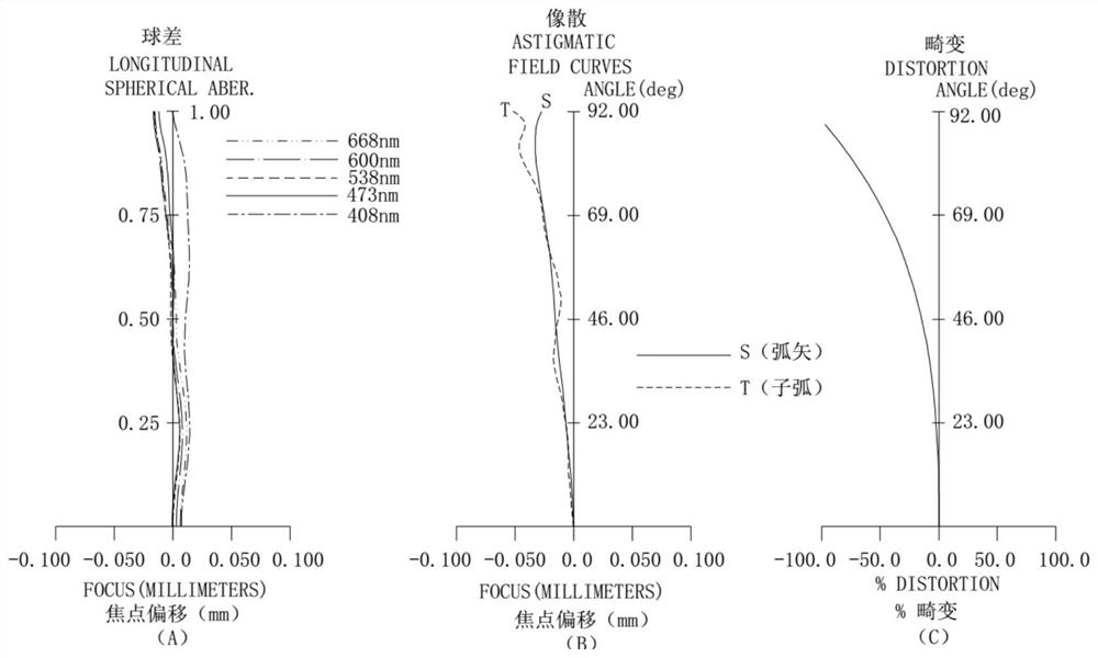
[0077] Specifically, with the effective focal length f=1.448mm of the optical lens 100, the aperture size FNO=2.05 of the optical lens 100, the field of view FOV=184deg of the optical lens 100, the total optical length of the optical lens 100 TTL=14.5mm is taken as an example, and other parameters of the optical lens 100 are given in Table 1 below. Wherein, the elements along the optical axis o of the...
no. 2 example
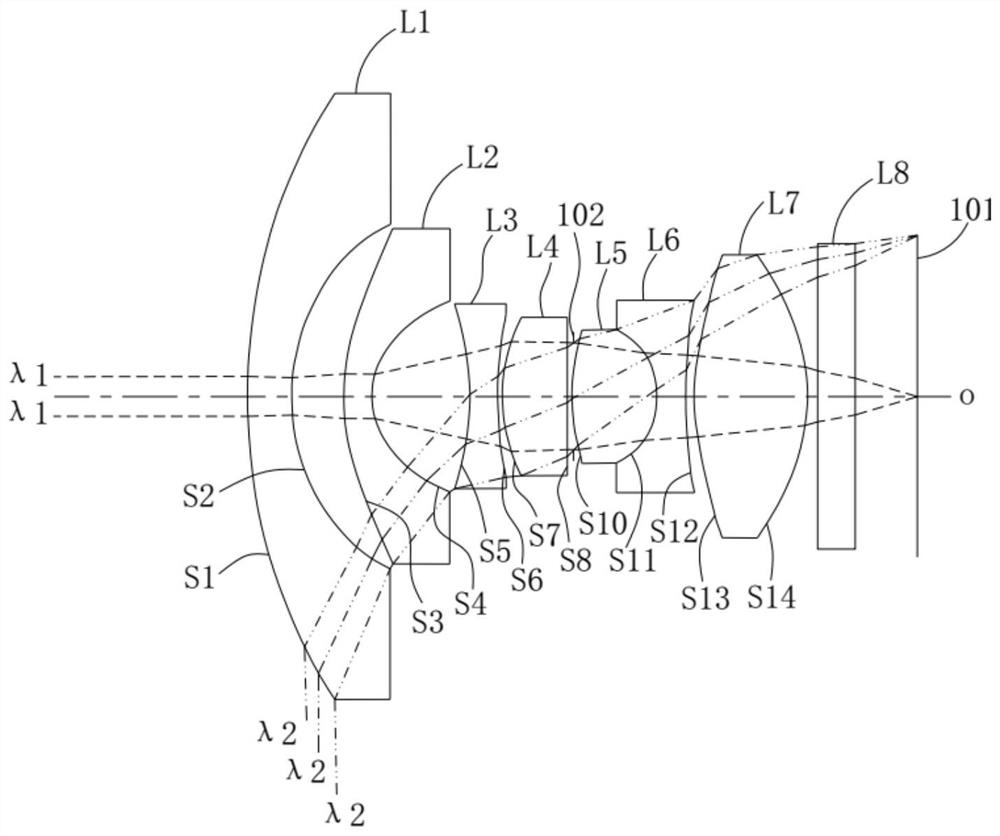
[0090] Please refer to image 3 , image 3 It is a schematic structural diagram of the optical lens 100 according to the second embodiment of the present application, and shows the optical paths of the paraxial ray λ1 and the marginal ray λ2. The optical lens 100 includes a first lens L1, a second lens L2, a third lens L3, a fourth lens L4, a diaphragm 102, a fifth lens L5, and a sixth lens arranged in sequence along the optical axis o from the object side to the image side. L6, seventh lens L7 and filter L8. Among them, regarding the material, refractive power and surface shape at the optical axis of the first lens L1, the second lens L2, the third lens L3, the fourth lens L4, the fifth lens L5, the sixth lens L6, and the seventh lens L7 Reference may be made to the description of the above specific implementation manners, and details are not repeated here.
[0091] In the second embodiment, with the effective focal length F=1.454mm of the optical lens 100, the aperture si...
no. 3 example
[0100] Please refer to Figure 5 , Figure 5 A schematic structural diagram of the optical lens 100 according to the third embodiment of the present application is shown, and the optical paths of the paraxial ray λ1 and the marginal ray λ2 are shown. The optical lens 100 includes a first lens L1, a second lens L2, a third lens L3, a fourth lens L4, a diaphragm 102, a fifth lens L5, and a sixth lens L6 arranged in sequence from the object side to the image side along the optical axis o , the seventh lens L7 and the filter L8. Among them, regarding the material, refractive power and surface shape at the optical axis of the first lens L1, the second lens L2, the third lens L3, the fourth lens L4, the fifth lens L5, the sixth lens L6, and the seventh lens L7 Reference may be made to the description of the above specific implementation manners, and details are not repeated here.
[0101] In the third embodiment, with the effective focal length F=1.316mm of the optical lens 100, ...
PUM
 Abstract
Description
Claims
Application Information
 - R&D
- Intellectual Property
- Life Sciences
- Materials
- Tech Scout
- Unparalleled Data Quality
- Higher Quality Content
- 60% Fewer Hallucinations
Browse by: Latest US Patents, China's latest patents, Technical Efficacy Thesaurus, Application Domain, Technology Topic, Popular Technical Reports.
© 2025 PatSnap. All rights reserved.Legal|Privacy policy|Modern Slavery Act Transparency Statement|Sitemap|About US| Contact US: help@patsnap.com


