
Wire and cable head peeling device

A wire and cable and wire end technology, which is applied in the field of wire and cable end stripping devices, can solve problems such as cutting labor, affecting splicing work, reducing cutting quality and efficiency, and achieving the effect of improving efficiency and quality

Inactive Publication Date: 2019-05-24
韩倩倩
View PDF0 Cites 0 Cited by
  • Summary
  • Abstract
  • Description
  • Claims
  • Application Information

AI Technical Summary

Problems solved by technology

[0002] In the actual use of wires and cables, it is usually necessary to remove the wire skin at the end of the wire and cable, and then splice it with another wire. When the wire and cable are peeled, clamps are generally used to cut, but this cutting is more laborious. And the cut end face is uneven, which reduces the quality and efficiency of cutting, and also affects the subsequent splicing work

Method used


Image

  • Wire and cable head peeling device
  • Wire and cable head peeling device
  • Wire and cable head peeling device

Examples


Embodiment Construction

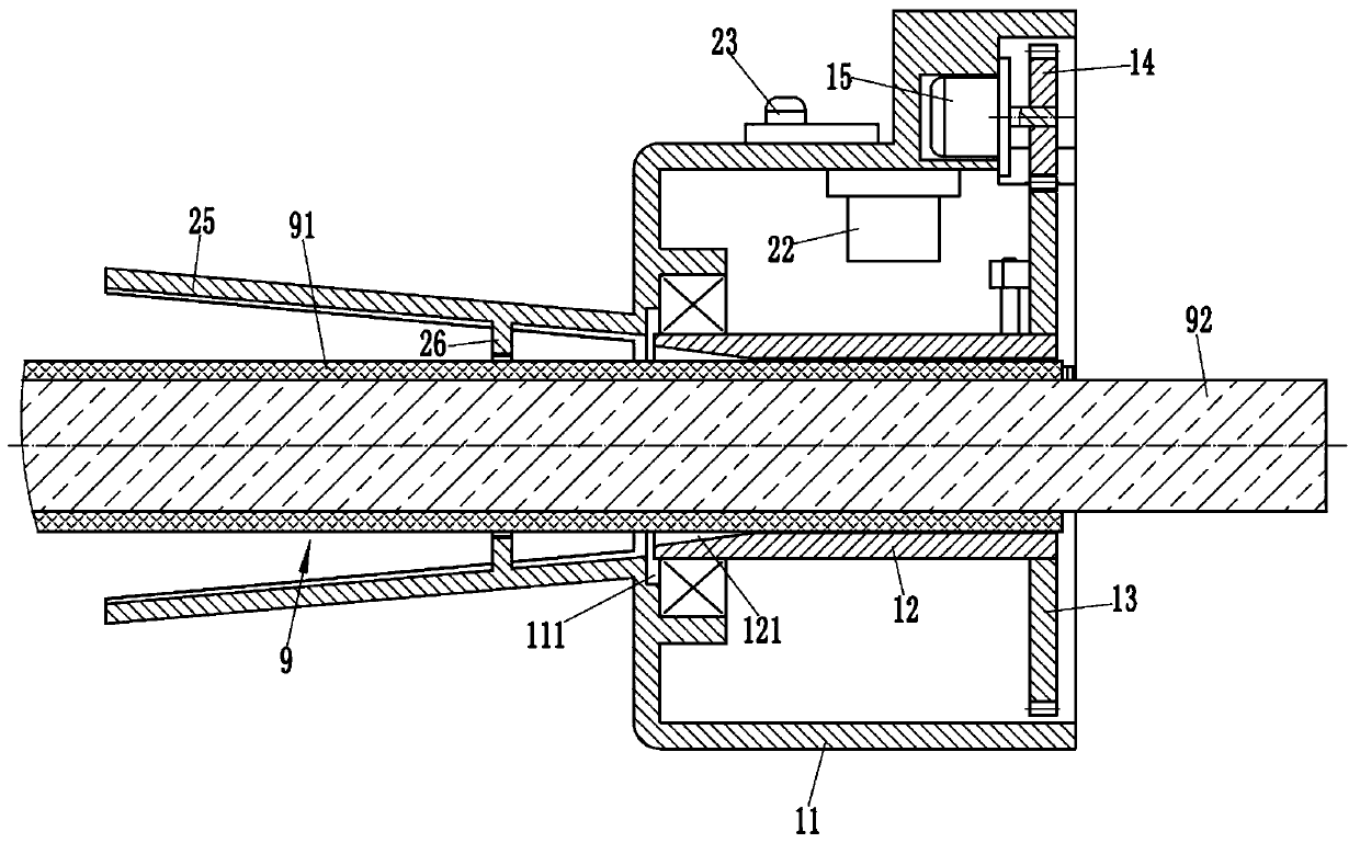
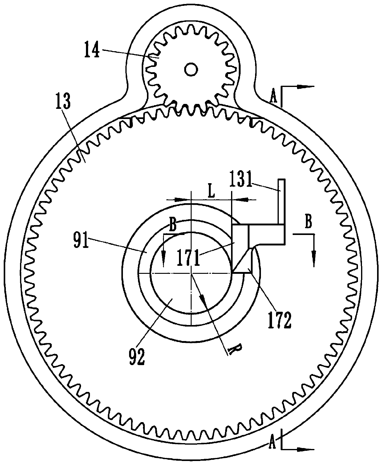
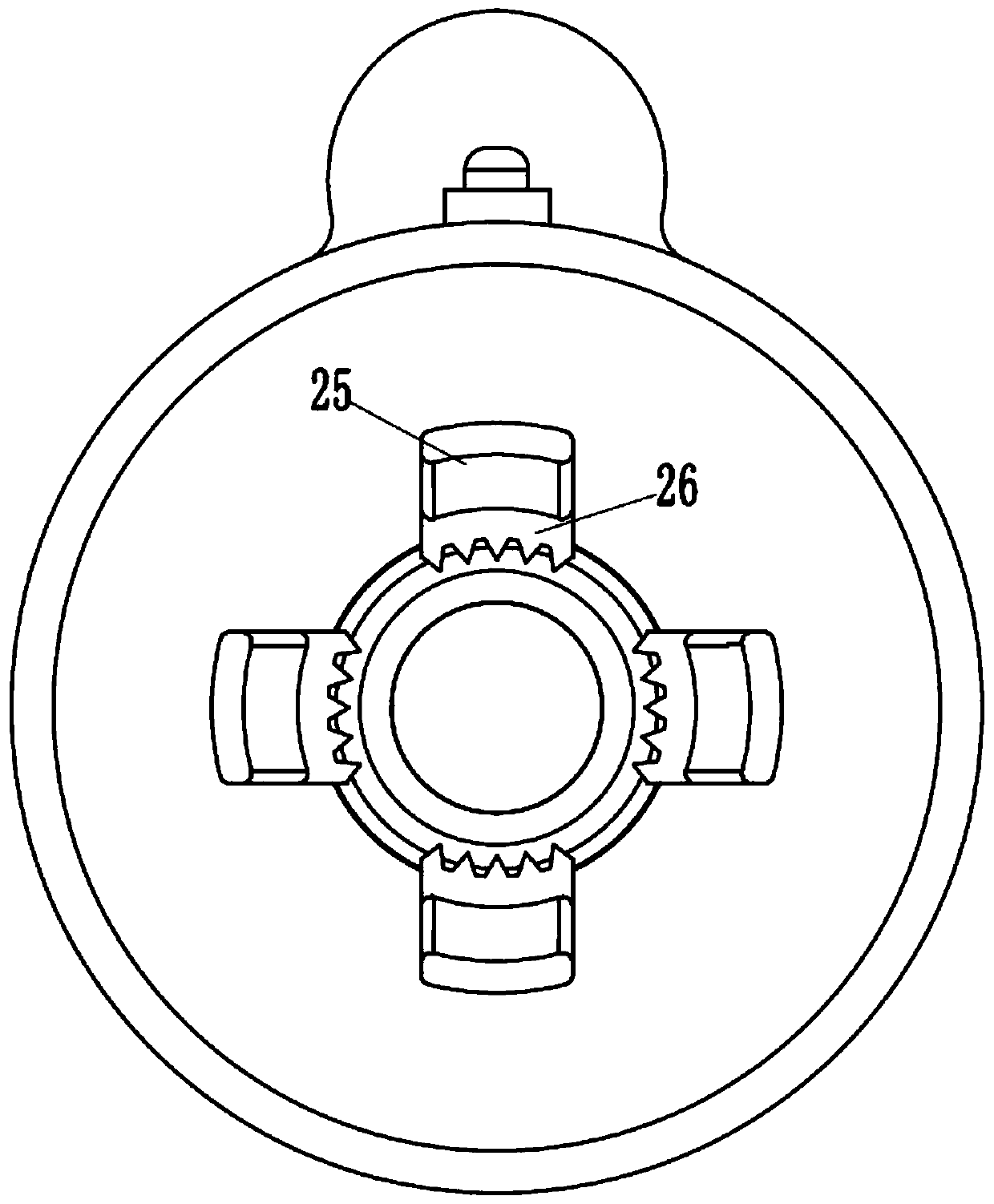
[0016] Examples, see e.g. Figure 1 to Figure 5 As shown, a wire and cable end stripping device includes a housing 11 with an opening on the right side, a bearing through hole 111 is formed on the left side wall of the housing 11, and a bearing through hole 111 is sleeved in the housing 11. The guide tube 12 arranged at the center of the shaft, the left end of the guide tube 12 is hinged in the bearing through hole 111 through the first bearing, the right end of the guide tube 12 is fixed with a large gear 13, and the upper end of the large gear 13 is meshed with a pinion 14, and the pinion 14 It is fixedly connected with the motor shaft of the first motor 15 fixed on the housing 11. The big gear 13 is formed with a rectangular hole 131 penetrating left and right, and a movable rectangular connecting arm 16 is sleeved in the rectangular hole 131. The rectangular connection The right extension end of the arm 16 passing through the rectangular hole 131 is fixed with a cutting kn...


PUM


Abstract

The invention discloses a wire and cable head peeling device. The device comprises a shell with a right opening. A guide pipe is hinged to the left side wall of the shell. A bull gear is fixed at theright end of the guide pipe. The upper end of the bull gear is meshed with a pinion. The pinion is fixedly connected with a motor shaft of a first motor fixed on the shell. A rectangular hole is formed in the bull gear. A movable rectangular connecting arm is sleeved in the rectangular hole. A cutter is fixed at the right end of the rectangular connecting arm. A first blade and a second blade which are vertically arranged are formed on the cutter. A nut is fixed to the left end of the rectangular connecting arm and is connected to a screw rod parallel to the rectangular hole in a threaded mode. The two ends of the screw rod are hinged to two hinge bases respectively. The hinge bases are fixed to the bull gear. One end of the screw rod is connected with a motor shaft of a second motor. According to the invention, the wire skin of the wire head part of a wire / cable can be automatically and quickly cut off. The peeling efficiency and the peeling quality are improved.

Description

Technical field: [0001] The invention relates to the technical field of cable and wire processing, in particular to a wire and cable end stripping device. Background technique: [0002] In the actual use of wires and cables, it is usually necessary to remove the wire skin at the end of the wire and cable, and then splice it with another wire. When the wire and cable are peeled, clamps are generally used to cut, but this cutting is more laborious. Moreover, the cut end face is uneven, which reduces the quality and efficiency of cutting, and also affects the subsequent splicing work. Invention content: [0003] The purpose of the present invention is to overcome the deficiencies of the prior art and provide a wire and cable end stripping device, which can automatically and quickly cut off the wire sheath at the end of the wire and cable, thereby improving the efficiency and quality of stripping. [0004] The scheme that the present invention solves described technical probl...

Claims


Application Information

Patent Timeline
IPC IPC(8): H01R43/28
Inventor 韩倩倩
Owner 韩倩倩
Learn More