
Power oscillation suppression system and method of grid-connected inverter

A power oscillation and inverter technology, applied in the electrical field, can solve the problems of increasing the hardware cost of the inverter, reducing the control response speed, complex parameter design, etc. Effect

Active Publication Date: 2019-05-24
WUHAN UNIV +1
View PDF2 Cites 8 Cited by
  • Summary
  • Abstract
  • Description
  • Claims
  • Application Information

AI Technical Summary

Problems solved by technology

The main problem of this method is that the parameter design is too complicated, the lead-lag calculation will inevitably reduce the control response speed, and it only works for a specific power grid; phase margin to suppress oscillation
The problem with this method is that the parameter design is too complicated, and it only works for a specific power grid; adaptive control measures the grid impedance in real time and uses its parameters to generate AC voltage, thereby using AC voltage feedforward to weaken the grid impedance The impact of changes on inverter control, suppressing oscillation problems caused by changes in grid impedance
The problem with this method is that additional current and voltage sensors need to be introduced, which increases the hardware cost of the inverter, and secondly, calculating the impedance will also reduce the control response speed, etc.

Method used


Image

  • Power oscillation suppression system and method of grid-connected inverter
  • Power oscillation suppression system and method of grid-connected inverter
  • Power oscillation suppression system and method of grid-connected inverter

Examples


Embodiment Construction

[0033] In order to facilitate those of ordinary skill in the art to understand and implement the present invention, the present invention will be described in further detail below in conjunction with the accompanying drawings and examples. It should be understood that the implementation examples described here are only used to illustrate and explain the present invention, and are not intended to limit the present invention. invention.

[0034] 1. Firstly, the system involved in the present invention will be introduced.

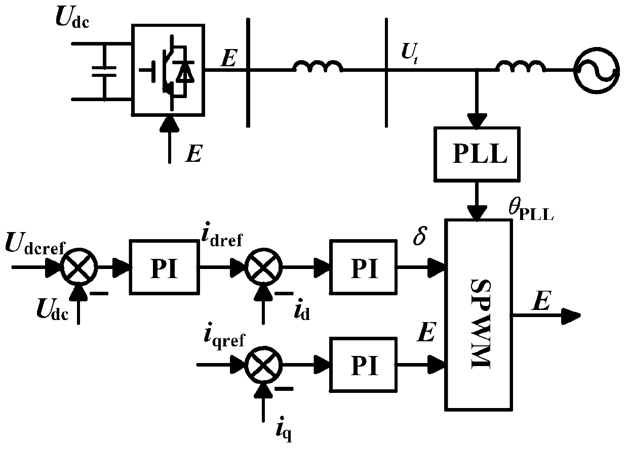
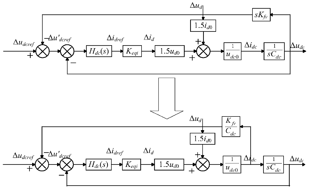
[0035] The invention mainly adds a voltage feedback device on the DC side, and the voltage feedback device is used to measure the instantaneous voltage value of the DC side and feed back to the input of the voltage loop and the current loop.

[0036] Voltage feedback devices include:

[0037] Resistor divider network, composed of resistors and measuring probes, used to measure the instantaneous value of DC side voltage;

[0038] The sampling filter module is...


PUM


Abstract

The present invention belongs to the field of electrical engineering and relates to a power oscillation suppression system and method of a grid-connected inverter. According to the method, a direct-current voltage differential component is fed back to a corresponding control link, and corresponding feedback parameter configuration is performed; and therefore, the suppression of the power oscillation of a grid-connected system can be realized, and the adaptability range and control parameter domain of a power grid can be greatly improved. The power oscillation suppression system of the grid-connected inverter of the invention has the advantages of obvious effects, simple structure, no increase in other external hardware costs, applicability for weak grids in a large range, and strong robustness to control loop parameter disturbances.

Description

technical field [0001] The invention relates to the field of electricity, in particular to a power oscillation suppression system and method for a grid-connected inverter. Background technique [0002] At present, common suppression algorithms for inverter grid-connected system oscillation include: lead-lag compensation method, virtual impedance method, adaptive control, etc. The lead-lag compensation method is to add a lead-lag compensator to the inverter current loop, and design the time constant of the lead-lag to increase the phase angle margin of the closed-loop system, so as to achieve the effect of improving stability and suppressing oscillation. The main problem of this method is that the parameter design is too complicated, the lead-lag calculation will inevitably reduce the control response speed, and it only works for a specific power grid; phase margin to suppress oscillations. The problem with this method is that the parameter design is too complicated, and it...

Claims


Application Information

Patent Timeline
Patent Type & Authority Applications(China)
IPC IPC(8): H02J3/38H02J3/24
Inventor 孙建军汪春江查晓明潘静曹志煌徐斌
Owner WUHAN UNIV
Learn More