A demodulator with a carrier generating pinned photodiode

A photodiode and demodulator technology, applied in the field of demodulators, to achieve high sensitivity, high fill factor, and improved demodulation speed

Active Publication Date: 2019-05-24
SONY DEPTHSENSING SOLUTIONS SA NV
View PDF12 Cites 2 Cited by
  • Summary
  • Abstract
  • Description
  • Claims
  • Application Information

AI Technical Summary

Problems solved by technology

Therefore, there is a tradeoff between demodulation speed and fill factor

Method used


Image

  • A demodulator with a carrier generating pinned photodiode
  • A demodulator with a carrier generating pinned photodiode
  • A demodulator with a carrier generating pinned photodiode

Examples


Embodiment Construction

[0048] In the following, the present disclosure will be presented with respect to a demodulator formed within a p-doped semiconductor layer. It should be understood that a person skilled in the art can easily implement the demodulator of the present disclosure within the n-doped semiconductor layer by exchanging the doping types of the different elements forming the demodulator.

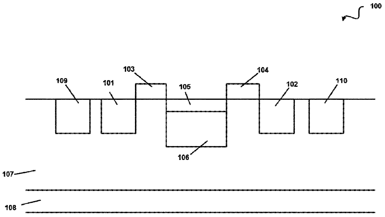
[0049] Figure 4 A top view of a demodulator 400 according to the present disclosure is shown. Figure 5 , Figure 6 and Figure 7 are the demodulator 400 of the present disclosure along Figure 4 Sectional views of lines C-D, E-F and G-H of .

[0050] The demodulator 400 of the present disclosure includes:

[0051] - A pinned photodiode for generating majority and minority carriers in response to an incident modulation signal. When the demodulator 400 is used for time-of-flight measurements, the modulated signal is modulated light reflected from the scene of interest.

[0052] - At least one st...


PUM


Abstract

The disclosure relates to a demodulator including a pinned photodiode, at least one storage node, at least one transfer gate connected between the storage node and the pinned photodiode. The pinned photodiode includes a p-doped epitaxial semiconductor layer, a n-doped semiconductor region formed within the epitaxial semiconductor layer and creating therewith a lower junction and at least one lateral junction substantially perpendicular to the lower junction, a p+ pinning layer formed on top of said semiconductor region. The demodulator further includes a generating unit configured to generateminority and majority carriers at said lateral junction and to form a lateral photodiode.

Description

technical field [0001] The present disclosure relates to a demodulator for receiving an optical signal as a modulated signal and an electrical signal as a demodulated signal. One of the applications of interest is time-of-flight measurements. Background technique [0002] Computer vision is an emerging field of research that includes methods for acquiring, processing, analyzing, and understanding images. The main driving idea in this field is the ability to replicate human vision by electronically perceiving and understanding images of a scene. Note that one topic of computer vision research is depth perception or, in other words, three-dimensional (3-D) vision. [0003] Time-of-flight (TOF) camera systems have emerged recently and are capable of capturing a 3-D image of a scene by timing the interval between the emission and the echo of a measured signal. This method is based on the principle that for a signal with a known velocity of propagation in a given medium, the d...

Claims


Application Information

Patent Timeline
Patent Type & Authority Applications(China)
IPC IPC(8): G01S7/491H01L27/146G01S7/4913
CPCG01S7/4913H01L27/14607H01L27/14609H01L27/14612H01L27/14856
Inventor 华德·范·德·腾佩尔
Owner SONY DEPTHSENSING SOLUTIONS SA NV
Why Eureka
Try Eureka