Method and device for determining linearization curve of printing equipment

A printing equipment and linearization technology, which is applied in the field of determining method and device for the linearization curve of printing equipment, can solve problems such as poor accuracy of Nelson coefficient, linearization curve of printing equipment does not conform to printing standards, etc., and achieve the effect of accurate generation

Active Publication Date: 2019-05-28
NEW FOUNDER HLDG DEV LLC +2
View PDF4 Cites 2 Cited by
  • Summary
  • Abstract
  • Description
  • Claims
  • Application Information

AI Technical Summary

Problems solved by technology

[0004] This application provides a method and device for determining the linearization curve of printing equipment, so as to solve the defects in the prior art

Method used


Image

  • Method and device for determining linearization curve of printing equipment
  • Method and device for determining linearization curve of printing equipment
  • Method and device for determining linearization curve of printing equipment

Examples


Embodiment 1

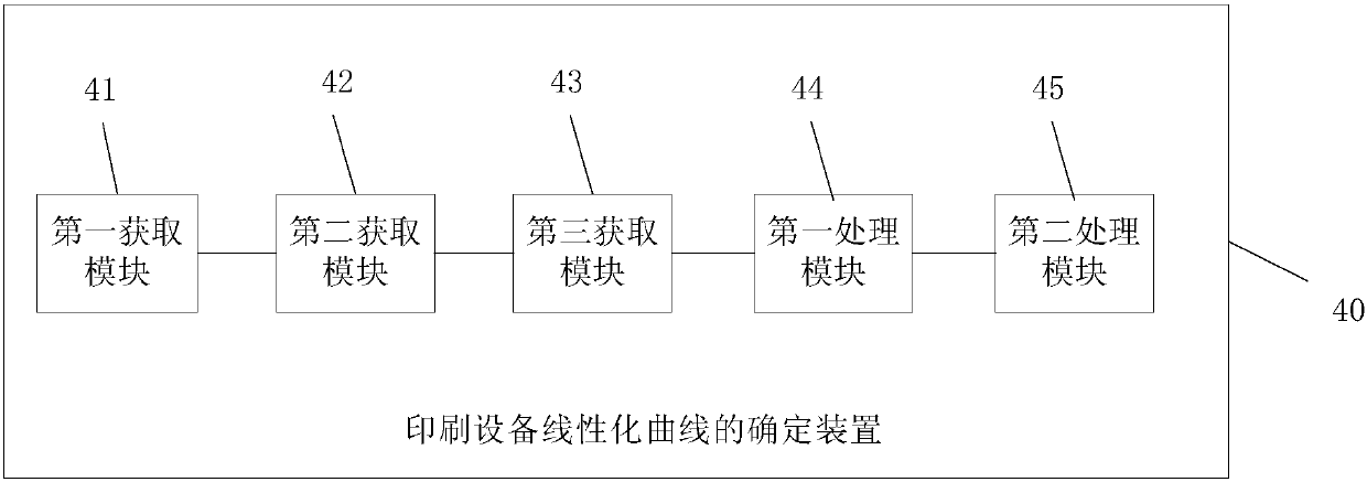
[0023] This embodiment provides a method for determining a linearization curve of a printing device, which is used for determining the linearization curve of a printing device. The executor of this embodiment is the device for determining the linearization curve of the printing equipment, and the device can be set in terminal devices such as servers, PCs, and tablet computers.

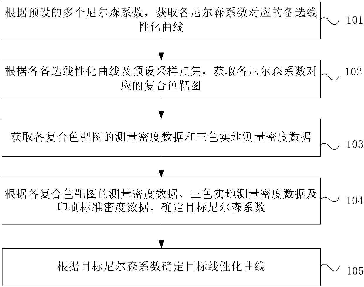
[0024] Such as figure 1 As shown, it is a schematic flow chart of the method for determining the linearization curve of the printing equipment provided in this embodiment, and the method includes:

[0025] Step 101 , according to a plurality of preset Nielsen coefficients, obtain an alternative linearization curve corresponding to each Nielsen coefficient.

[0026] Step 102, according to each candidate linearization curve and the preset sampling point set, obtain the composite color target map corresponding to each Nelson coefficient.

[0027] Step 103, acquiring the measured density data of each com...

Embodiment 2

[0033] This embodiment provides a further supplementary description of the method for determining the linearization curve of the printing device provided in the first embodiment.

[0034] As an implementable manner, on the basis of the first embodiment above, optionally, step 101 may specifically include:

[0035] Step 2011, obtain the ladder color target map according to the set of preset input points.

[0036] Step 2012, acquiring the scale measurement density and the scale maximum measurement density of the scale color target image.

[0037] Step 2013, obtain the corresponding standard reference density according to the maximum measured density of the ladder scale and a plurality of preset Nelson coefficients.

[0038] Specifically, the following formula (1) is used to obtain the corresponding standard reference density:

[0039]

[0040] Among them, D s is the maximum measured density of the ladder, N is the Nielsen coefficient, X i Represents the value of the i-th ...

Embodiment 3

[0073] This embodiment further describes in detail the method for determining the linearization curve of the printing device provided in the above embodiments.

[0074] The method may specifically include the following four steps:

[0075] Step 1. Obtain multiple linearization curves corresponding to multiple Nelson coefficients

[0076] Setting the linearization curve of k printing equipment is represented by the following expression:

[0077] In={X 1 ,X 2 ,...,X i ,...,X m} X i ∈[0,100]

[0078] Out={Out 1 ,Out 2 ,...,Out j ,...,Out k} j∈[1,k]

[0079] out j ={Y 1 ,Y 2 ,...,Y i ,...,Y m} Y i ∈[0,100]

[0080] Among them: In represents the set of input points (the unit is a percentage), m represents the number of In, X i Represents the value of the input point; Out represents the output point set of k linearization curves; Out j Indicates the set of output points of the jth equipment linearization curve, Y i Represents X in the jth linearization curve i ...


PUM


Abstract

The invention provides a method and a device for determining a linearization curve of a printing equipment. The method for determining the linearization curve of the printing equipment comprises the following steps of according to a preset number of nilson coefficients, and obtaining an alternative linearization curve corresponding to the nigelson coefficient; according to each alternative linearization curve and a preset sampling point set, and obtaining a composite color target graph corresponding to the nigelson coefficients; acquiring measurement density data and three-color on-site measurement density data of each composite color target graph; according to the measurement density data of the composite color target graph, three-color on-site measurement density data and printing standard density data, and determining a target nilson coefficient; and according to the target nilson coefficient, and determining a target linearization curve. According to the method and the device for determining the linearization curve of the printing equipment, the automatic determination of the nison coefficient value is realized, the target linearization curve conforms to the printing standard is generated, so that the purpose of scientifically and accurately generating the linear curve of the equipment is achieved, and a foundation is laid for further color management.

Description

technical field [0001] The present application relates to the field of printing technology, in particular to a method and device for determining a linearization curve of a printing device. Background technique [0002] With the development of technologies such as digital proofing and digital printing, color management plays an increasingly important role in printing production. Therefore, improving printing efficiency through the combination of color management and printing technology has become a research hotspot. In the existing printing process, due to the fact that the original output state of the inkjet output device is not linear, the gradation and level of the output printed product are not ideal, and there are problems such as ink accumulation and color shift, which are not suitable for further color management. In order to improve the quality of printed products, it is necessary to linearize the output device. [0003] Equipment linearization is based on paper and...

Claims


Application Information

Patent Timeline
IPC IPC(8): B41F33/00
Inventor 闫雪艳李海峰王剑
Owner NEW FOUNDER HLDG DEV LLC
Why Eureka
Try Eureka