Stone carving machine

A technology of engraving machine and stone, applied in decorative arts, processing models, etc., can solve the problems of inconvenient maintenance and cleaning, and achieve the effect of good waterproof effect

Pending Publication Date: 2019-05-28
吴善旺
View PDF1 Cites 1 Cited by
  • Summary
  • Abstract
  • Description
  • Claims
  • Application Information

AI Technical Summary

Problems solved by technology

[0004] The purpose of the present invention is to solve the problem of inconvenient maintenance and cleaning of the existing stone engraving machine after the waterproof effect is guaranteed.

Method used


Image

  • Stone carving machine
  • Stone carving machine
  • Stone carving machine

Examples


Embodiment 1

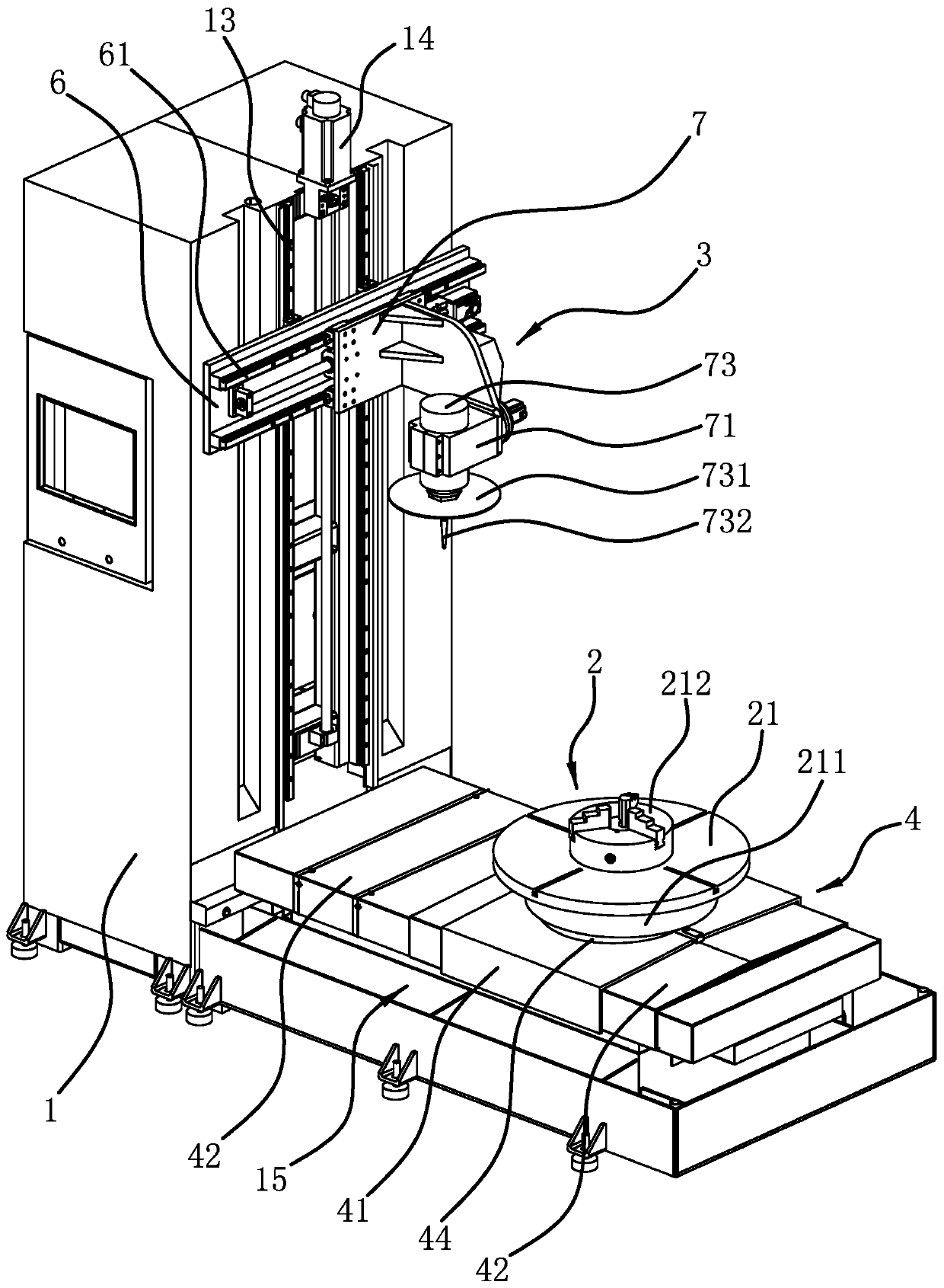
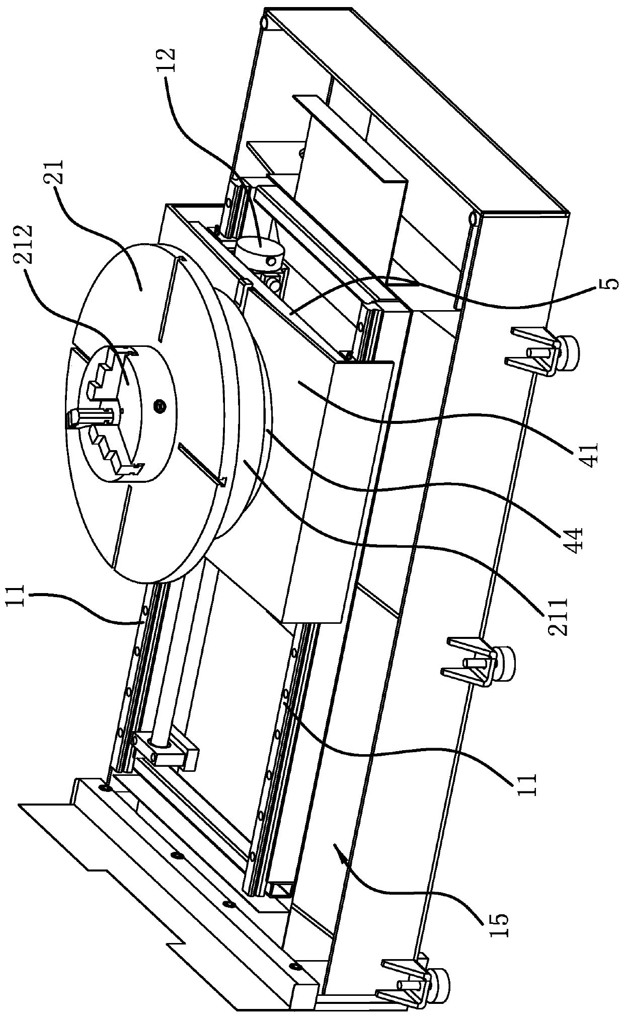
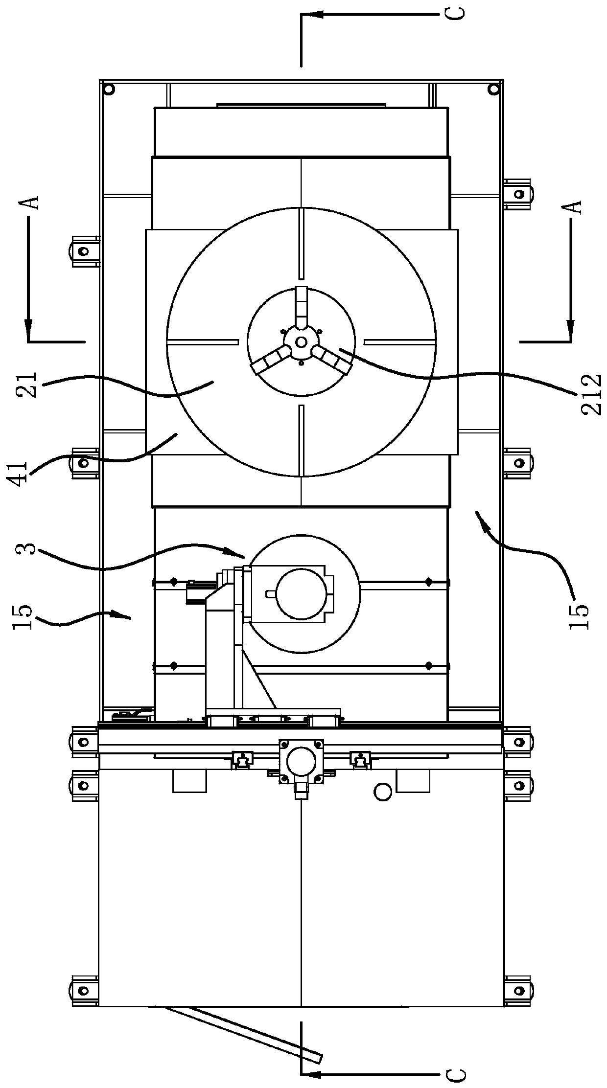
[0035] Such as figure 1 As shown, a stone engraving machine includes a frame 1, a processing assembly 3 and a processing table 2, a pair of vertical slide rails 13 are vertically fixed on the top of the frame 1, and vertical slide rails 13 are slidably connected with vertical The carriage 6 is also provided with a vertical motor 14 on the frame 1, and the vertical motor 14 drives the vertical carriage 6 to slide vertically through the cooperation of the screw nut. A pair of horizontal slide rails 61 are horizontally fixed on the vertical carriage 6, and the horizontal carriage 7 is slidably connected to the horizontal slide rails 61. A horizontal motor 62 is also arranged on the vertical carriage 6, and the horizontal motor 62 passes through a screw nut. Cooperate to drive the horizontal carriage 7 to slide laterally. A rotatable steering seat 71 is connected on the horizontal carriage 7, and the rotation axis of the steering seat 71 is arranged laterally. Saw disc 731 and e...

Embodiment 2

[0039] The structure of the stone engraving machine is basically the same as that of Embodiment 1, the difference is that Figure 10 As shown, the diversion sleeve 211 includes an outer body 2111 and an inner body 2112, the upper part of the outer body 211 is fixedly connected to the lower side of the turntable 21, the upper part of the inner body 2112 is located inside the lower part of the outer body 2111, and the inner body 2112 The top and the bottom of the outer casing 2111 are fixedly connected by screws, and the distance from the lower edge of the outer casing 2111 to the upper side of the waterproof cover 4 is greater than the height of the waterproof cover 44.

Embodiment 3

[0041] The structure of this stone engraving machine is basically the same as the second embodiment, the difference is that Figure 11 As shown, the inner sleeve body 2112 includes two arc-shaped deflectors 2113, the two ends of the two deflectors 2113 are respectively butted to form the inner sleeve body 2112, the distance from the lower edge of the outer sleeve body 2111 to the upper side of the waterproof cover 4 Greater than the height of the inner sleeve body 2112, the two deflectors 2113 can be directly removed at the screw loosening opening to facilitate the disassembly and assembly of the waterproof cover 44.


PUM


Abstract

The invention provides a stone carving machine, and belongs to the technical field of mechanical processing equipment. The invention solves the problem that the existing stone carving machine is inconvenient to overhaul and clean after ensuring the waterproof effect. The stone carving machine comprises a frame and a processing table, wherein the frame is slidingly provided with a movable draggingplate along a horizontal direction; the movable dragging plate is provided with a waterproof cover; the waterproof cover is arranged on the movable dragging plate; an avoidance hole is formed in the waterproof cover; the processing table is positioned above the waterproof cover; the lower part of the processing table passes through the avoidance hole and is rotationally connected with the movabledragging plate or the upper part of the movable dragging plate passes through the avoidance hole and is rotationally connected with the processing table; the upper side surface of the waterproof coveris provided with an annular waterproof sleeve which is arranged around the avoidance hole; and the lower side surface of the processing table is provided with an annular diversion sleeve which surrounds the outer side of the waterproof sleeve. The stone carving machine is more convenient to overhaul and clean while ensuring the waterproof effect.

Description

technical field [0001] The invention belongs to the technical field of mechanical processing equipment, and relates to a stone engraving machine. Background technique [0002] From the processing principle, engraving is a combination of drilling and milling. It has a wide range of applications, including woodworking engraving machines, laser engraving machines, advertising engraving machines, jade engraving machines, stone engraving machines, cylindrical engraving machines, etc. The engraving machine has a wide range of applications. Widely used, and even replaced the hand-carving technology, which laid the foundation for the mass and rapid production of products. Among them, such as the stone engraving machine, in the process of engraving the stone, it is necessary to spray water on the engraving position, and the water stains will flow along the stone to the engraving machine frame, so it is necessary to waterproof the guide rails, motors and other components under the eng...

Claims


Application Information

Patent Timeline
Patent Type & Authority Applications(China)
IPC IPC(8): B44B1/00B44B1/06
Inventor 吴善旺
Owner 吴善旺
Why Eureka
Try Eureka