

Hydraulic engineering sludge separation device
A separation device and water conservancy engineering technology, applied in water/sludge/sewage treatment, dehydration/drying/concentrated sludge treatment, sludge treatment, etc., can solve problems such as equipment damage, and achieve the effect of avoiding residues
- Summary
- Abstract
- Description
- Claims
- Application Information
AI Technical Summary
Problems solved by technology
Method used
Image

Examples
Embodiment 1
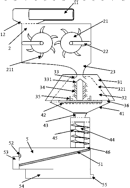
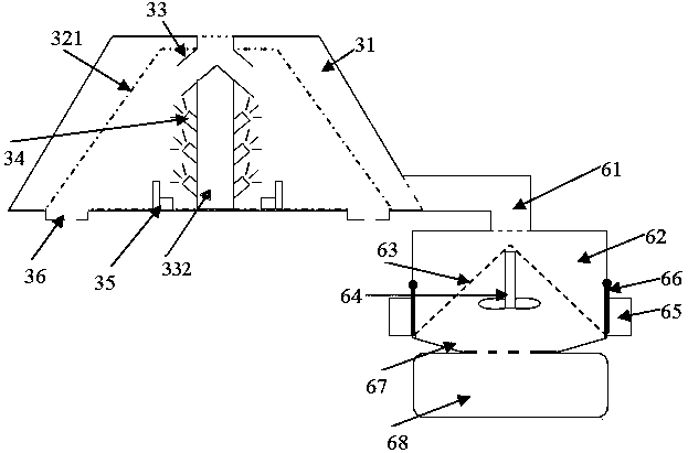
[0031] Such as figure 1 with figure 2 Shown: a water conservancy project sludge separation device, including a mud suction chamber, a crushing chamber, a separation chamber, a stirring and pushing chamber, a stone removal chamber and a sewage treatment chamber.
[0032] The suction chamber includes a suction chamber casing, a suction pump and an outlet of the suction chamber; the casing of the suction chamber is arranged in a transverse cylindrical structure, and a suction pump is arranged at one end inside it, and a suction pump is arranged at the lower part of the other end. Mud room egress.
[0033] The crushing chamber includes a crushing chamber shell, two crushing roller assemblies, an inlet of the crushing chamber and an outlet of the crushing chamber; the crushing roller assembly includes a crushing roller, crushing teeth arranged on the crushing roller and a support frame for fixing the crushing roller , the crushing teeth are arranged on the outer surface of the c...
Embodiment 2
[0046] A water conservancy project sludge separation device comprises a mud suction chamber, a crushing chamber, a separation chamber, a stirring and pushing chamber, a stone removal chamber and a sewage treatment chamber.
[0047] The suction chamber includes a suction chamber casing, a suction pump and an outlet of the suction chamber; the casing of the suction chamber is arranged in a transverse cylindrical structure, and a suction pump is arranged at one end inside it, and a suction pump is arranged at the lower part of the other end. Mud room egress.
[0048] The crushing chamber includes a crushing chamber shell, 3 groups of 6 crushing roller assemblies, the crushing chamber inlet and the crushing chamber outlet; the crushing roller assembly includes crushing rollers, crushing teeth arranged on the crushing rollers and a bracket for fixing the crushing rollers. The supporting frame, the crushing teeth are arranged in a half-crescent shape on the outer surface of the crus...
Embodiment 3
[0059] A water conservancy project sludge separation device comprises a mud suction chamber, a crushing chamber, a separation chamber, a stirring and pushing chamber, a stone removal chamber and a sewage treatment chamber.
[0060] The suction chamber includes a suction chamber casing, a suction pump and an outlet of the suction chamber; the casing of the suction chamber is arranged in a transverse cylindrical structure, and a suction pump is arranged at one end inside it, and a suction pump is arranged at the lower part of the other end. Mud room egress.
[0061] The crushing chamber includes a crushing chamber shell, three crushing roller assemblies, a crushing chamber inlet and a crushing chamber outlet; the crushing roller assembly includes a crushing roller, crushing teeth arranged on the crushing roller and a support frame for fixing the crushing roller , the crushing teeth are arranged on the outer surface of the crushing roller in a half-crescent shape, and the crushin...
PUM
 Abstract
Description
Claims
Application Information