SBW (steer-by-wire) device with redundancy function and control method
A technology of steering by wire and function, which is applied in the direction of mechanical steering gear and electric steering mechanism, which can solve the problem that the vehicle can still be turned normally, and achieve the effect of ensuring safety
- Summary
- Abstract
- Description
- Claims
- Application Information
AI Technical Summary
Problems solved by technology
Method used
Image
Examples
Embodiment 1
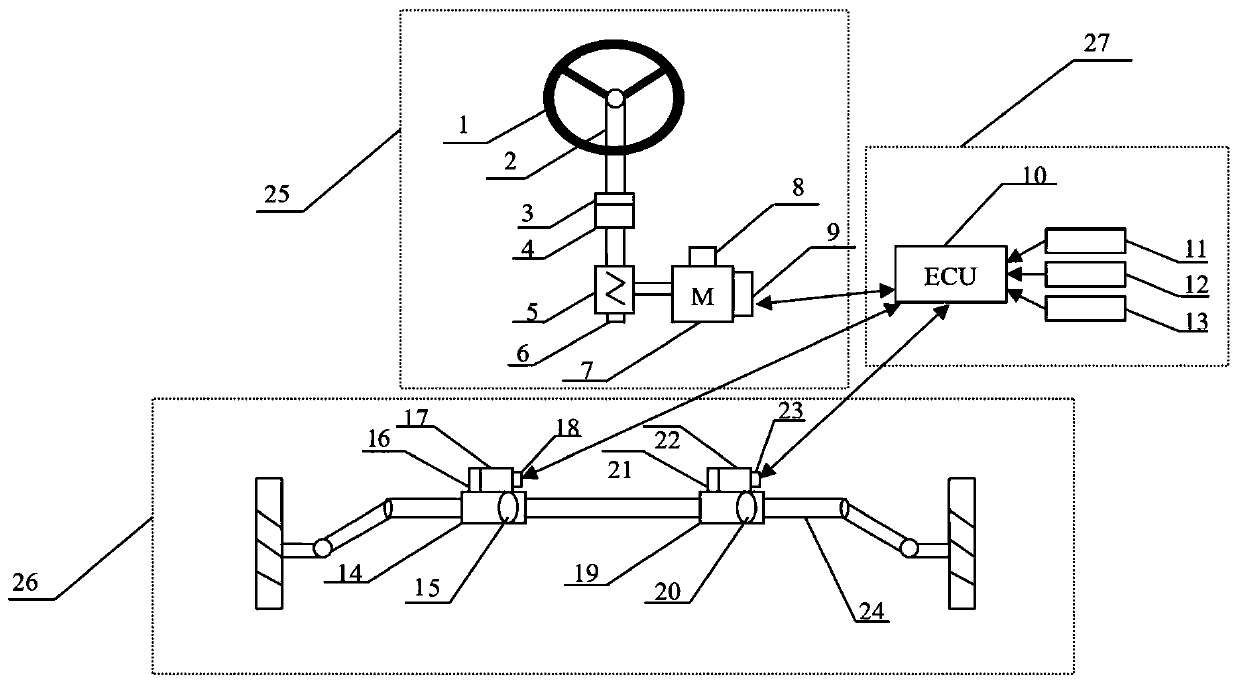
[0029] This embodiment provides a steering-by-wire device with redundant functions, and its structure can be found in figure 1 , including road sense simulation actuators, steering actuators and steer-by-wire control modules.
[0030] Wherein, the road sense simulation actuator 25 includes a steering wheel 1, a steering input shaft 2, a torque sensor 3, a first angle sensor 4, a worm gear mechanism 5, a second angle sensor 6, a road sense motor 7, and a road sense motor rotor position sensor 8 And road sense motor controller9.
[0031] The steering wheel 1 is connected with the steering input shaft 2 to obtain the driver's driving intention. A torque sensor 3 and a first rotation angle sensor 4 are installed between the steering input shaft 2 and the worm gear 5 to detect the driver's hand force and the steering wheel's corner.
[0032] The road sense motor 7 is connected to the steering input shaft 2 through the worm gear mechanism 5 to simulate the road sense feedback torq...
Embodiment 2
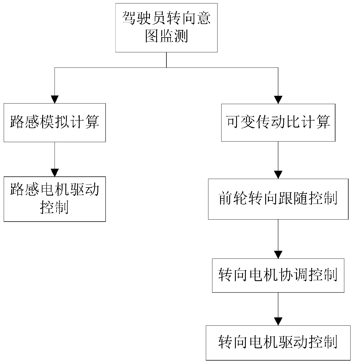
[0052] refer to image 3 , this embodiment provides a control method for a steering-by-wire device with a redundant function, which is used to control the steering-by-wire device with a redundant function as described in Embodiment 1, and includes:
[0053] S10. Identify the driver's steering behavior by collecting information such as vehicle speed, steering wheel angle, steering wheel speed, vehicle yaw acceleration, and vehicle lateral acceleration;
[0054] S20. Estimating the steering resistance when the vehicle is running through the identification of the driver's steering behavior, and completing the estimation of the road feeling information of the current driving condition. The flow chart of road sense simulation control (estimation of road sense information) is as follows: Figure 4 As shown, it includes four parts: steering load observation, virtual power assist control, corner limit control and road sense torque synthesis.
[0055] 1) Steering load observation, wh...
PUM
 Abstract
Description
Claims
Application Information
 - R&D
- Intellectual Property
- Life Sciences
- Materials
- Tech Scout
- Unparalleled Data Quality
- Higher Quality Content
- 60% Fewer Hallucinations
Browse by: Latest US Patents, China's latest patents, Technical Efficacy Thesaurus, Application Domain, Technology Topic, Popular Technical Reports.
© 2025 PatSnap. All rights reserved.Legal|Privacy policy|Modern Slavery Act Transparency Statement|Sitemap|About US| Contact US: help@patsnap.com


