

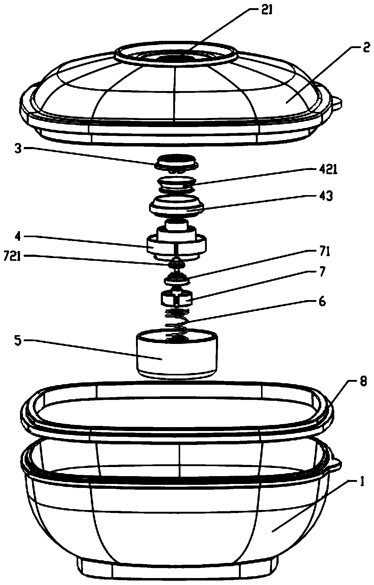
Vacuum air pumping and deflating container
A vacuum and container technology, which can be applied to packaging under vacuum/special atmosphere, packaging objects under special gas conditions, and closing, etc., can solve the problems of low product popularity, difficult to open containers, and insufficient pressure holding time, etc. High-quality storage and packaging experience, reliable and long-lasting pressure holding time, and convenient pumping and deflation effects
- Summary
- Abstract
- Description
- Claims
- Application Information
AI Technical Summary
Problems solved by technology
Method used
Image

Examples
Embodiment 1
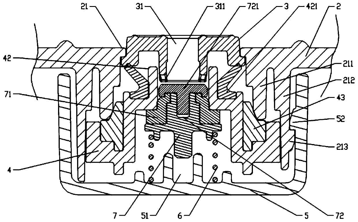
[0039] When performing air extraction work, take the air extraction device 9 and insert it into the sealing air nozzle from the air hole 31' of the button 3', the air extraction device 9 will press down the sealing assembly, and the piston sealing ring 71' and the cylindrical air guide hole of the sealing bracket 4' A gap is formed between 42'. At this time, the inner cavity of the container, the gap between the inner wall of the valve bottom cover 5' and the outer wall of the valve installation port 21', the ventilation square groove 41' of the sealing bracket 4, and the piston sealing ring The gap between 71' and the cylindrical air guide hole 42' of the sealing bracket 4' forms an air path, through which the air in the container is drawn out by the air extraction device, and a highly decompressed environment is formed in the container.
Embodiment 2
[0041]When performing deflation work, press the button 3" down, the button 3" will press down the sealing assembly, and a gap will be formed between the piston sealing ring 71" and the cylinder air guide hole 42" of the sealing bracket 4", at this time, the button 3" air hole 31", air hole 31" at the bottom of the circular groove 311", the gap between the piston sealing ring 71" and the cylindrical air hole 42" of the sealing bracket 4", the ventilation square groove 41" of the sealing bracket 4", the air The gap between the inner wall of the nozzle bottom cover 5" and the outer wall of the air nozzle installation port 21" forms an air path, and the external air enters the container through the air path to balance the internal and external air pressure, and the container cover 2" can be easily opened.
PUM
 Abstract
Description
Claims
Application Information