Liquid lifting device for accelerating aging of liquor with power ultrasonic waves

A liquid lifting and ultrasonic technology, which is used in the field of liquor aging, can solve the problems of liquid transportation that cannot be equal in volume and different liquid volumes.

Inactive Publication Date: 2019-05-28
HEILONGJIANG LANDE ULTRASONIC TECH CO LTD
View PDF1 Cites 0 Cited by
  • Summary
  • Abstract
  • Description
  • Claims
  • Application Information

AI Technical Summary

Problems solved by technology

However, during the actual use of the equipment, the hydraulic pressure will decrease with the decrease of the liquid level, and the reduction of the hyd

Method used


Image

  • Liquid lifting device for accelerating aging of liquor with power ultrasonic waves
  • Liquid lifting device for accelerating aging of liquor with power ultrasonic waves
  • Liquid lifting device for accelerating aging of liquor with power ultrasonic waves

Examples


specific Embodiment approach 1

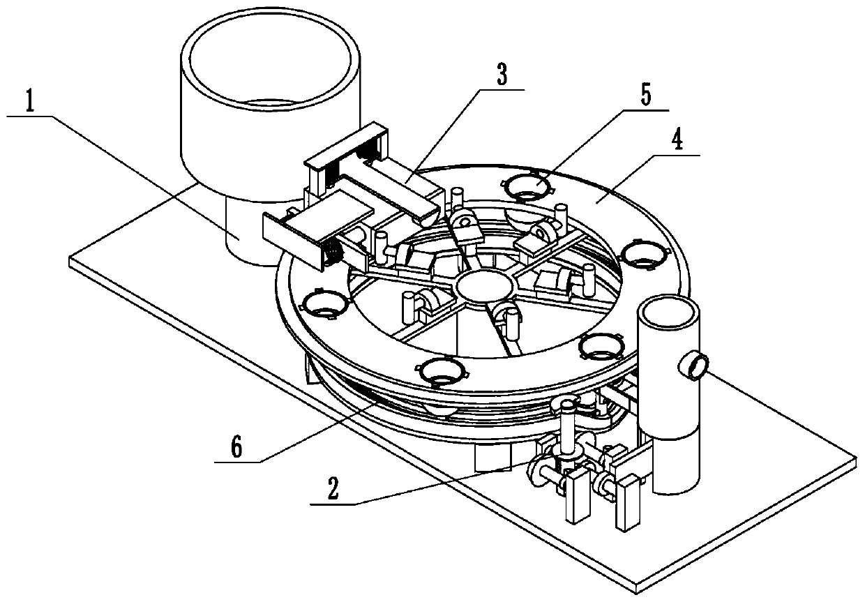
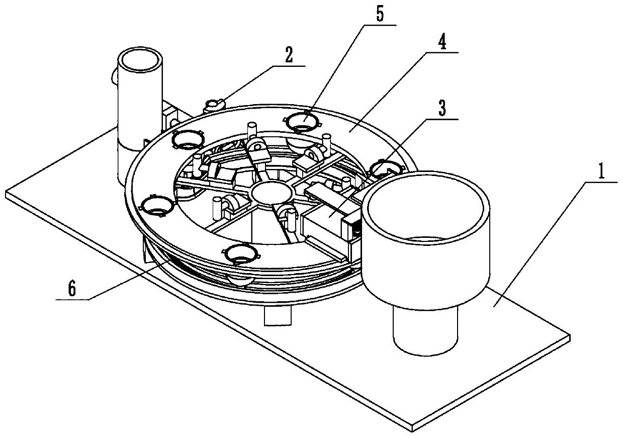
[0032] Such as Figure 1 to Figure 13 As shown, the power ultrasonic liquor aging liquid lifting device includes a material storage lifting base 1, a driver 2, a slow flow device 3, a rotating flow divider 4, six homogeneous transporters 5 and a sliding base 6, the described The driver 2 is rotatably connected to the material storage lifting base 1, the driver 2 is engaged with the rotating diverter 4 for transmission, the rotating diverter 4 is rotatably connected to the material storage lifting base 1, and the rotating diverter 4 is slidably connected to the slow flow device 3 Inside, the slow flow device 3 is fixedly connected to the material storage lifting base 1, the six homogeneous conveyors 5 are evenly plugged into the rotating diverter 4, and the six homogeneous conveyors 5 are all slidably connected to the sliding base 6 , the sliding base 6 is fixedly connected on the storage lifting base 1. Driven by the driver 2, the liquor stored in the storage lifting base 1 i...

specific Embodiment approach 2

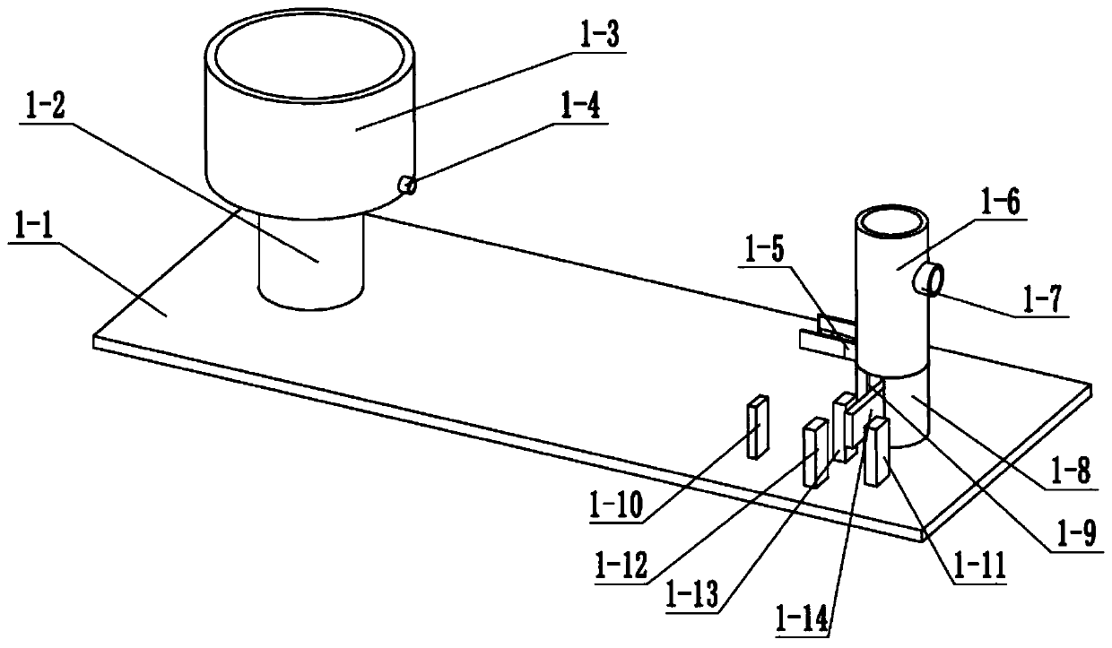
[0033] Such as Figure 1 to Figure 13 As shown, this embodiment will further explain Embodiment 1. The storage lifting base 1 includes a bottom plate 1-1, a storage tank base 1-2, a storage tank 1-3, a discharge pipe 1-4, Drainage frame 1-5, lifting cylinder 1-6, recovery pipe 1-7, fixed bottom frame 1-8, sliding opening 1-9, first rotating seat 1-10, second rotating seat 1-11, third rotating seat Seat 1-12, the fourth rotating seat 1-13, drive rack 1-14, push rod 1-15, receive push seat 1-16 and push sealing ring 1-17, storage tank base 1-2, fix The bottom frame 1-8, the first rotating seat 1-10, the second rotating seat 1-11, the third rotating seat 1-12 and the fourth rotating seat 1-13 are all fixedly connected on the base plate 1-1, and the material storage cylinder 1-3 is fixedly connected to the storage tank base 1-2, the discharge pipe 1-4 is fixedly connected to the right end of the storage tank 1-3, and the drainage frame 1-5 is fixedly connected to the lower side o...

specific Embodiment approach 3

[0034] Such as Figure 1 to Figure 13 As shown, this embodiment further explains the second embodiment, the driver 2 includes a servo motor 2-1, a main shaft 2-2, a main drive bevel gear 2-3, a semicircular drive gear 2-4, a double-toothed Drive gear 2-5, the first rotating shaft 2-6, the first driving circular gear 2-7, the second driving circular gear 2-8, the second driving rotating shaft 2-9, the first semicircle driving gear 2-10, the third Drive shaft 2-11, second semicircular drive gear 2-12, reciprocating drive gear 2-13, reciprocating drive shaft 2-14 and driven reciprocating drive gear 2-15, servo motor 2-1 is fixedly connected to base plate 1-1 Above, the main rotating shaft 2-2 is connected to the transmission shaft of the servo motor 2-1 through a coupling, the main driving bevel gear 2-3 is fixedly connected to the main rotating shaft 2-2, and the semicircular driving gear 2-4 is fixedly connected to the main rotating shaft 2 -2, the main driving bevel gear 2-3 ...


PUM


Abstract

The invention relates to the field of accelerating aging of liquor, in particular to a liquid lifting device for accelerating aging of liquor with power ultrasonic waves, which comprises a storage lifting base, a driver, a flow damper, a rotation flow divider, six homogeneous conveyors and a sliding base. The driver is rotatably connected to the storage lifting base and is in engaged transmissionwith the rotation flow divider. The rotation flow divider is rotatably connected to the storage lifting base and slidably connected in the flow damper. The flow damper is fixedly connected to the storage lifting base. The six homogeneous conveyors are evenly inserted to the rotation flow divider. The liquid lifting device has the beneficial effect of conveying the liquor stored in a cellar or a well in a sealed mode onto the ground intermittently in batches with the same volume for bottling the liquor.

Description

technical field [0001] The invention relates to the field of aging aging of liquor, more specifically a liquid lifting device for accelerating aging of liquor with power ultrasonic waves. Background technique [0002] Patent No. CN201510707255.6 discloses an intermittent automatic filling equipment, which relates to the technical field of filling tools. The equipment includes two symmetrically arranged liquid storage chambers, and an intermittent liquid Lifting device, the liquid inlet end of the intermittent liquid lifting device is connected to the liquid storage chamber, the liquid outlet end of the intermittent liquid lifting device is located above the intermittent filling device, and the intermittent liquid lifting device and the intermittent filling device are connected to each other Cooperate with synchronized movement. The equipment can be filled automatically, and the volume of liquid is the same every time. However, in the actual use of the device, the hydraulic...

Claims


Application Information

Patent Timeline
IPC IPC(8): B67D7/02B67D7/06
Inventor 单长城张健任耀军窦如胜
Owner HEILONGJIANG LANDE ULTRASONIC TECH CO LTD
Why Eureka
Try Eureka