
Luminous composition, luminous layer containing luminous composition and electroluminescence device

A technology of composition and general formula, applied in the field of organic electroluminescent materials, can solve problems such as concentration quenching, lack of host materials, and low efficiency of blue light-emitting devices

Inactive Publication Date: 2019-05-28
AAC TECH NANJING
View PDF9 Cites 14 Cited by
  • Summary
  • Abstract
  • Description
  • Claims
  • Application Information

AI Technical Summary

Problems solved by technology

[0008] Although organic light-emitting materials have made great progress, such as red and green phosphorescent materials have been commercialized, and blue fluorescent materials are also widely used in organic electroluminescent devices, the commercialization of blue phosphorescent materials is slow. And difficult, because the blue material in commercialization is a blue fluorescent material, the efficiency of blue light-emitting devices has not been high
There are two main problems in blue light-emitting devices: one is that stable blue phosphorescent materials are very scarce, and the other is the lack of host materials with high triplet energy.
Although the guest material has high luminous efficiency, it also has the problem of concentration quenching.

Method used


Image

  • Luminous composition, luminous layer containing luminous composition and electroluminescence device
  • Luminous composition, luminous layer containing luminous composition and electroluminescence device
  • Luminous composition, luminous layer containing luminous composition and electroluminescence device

Examples


Embodiment 1

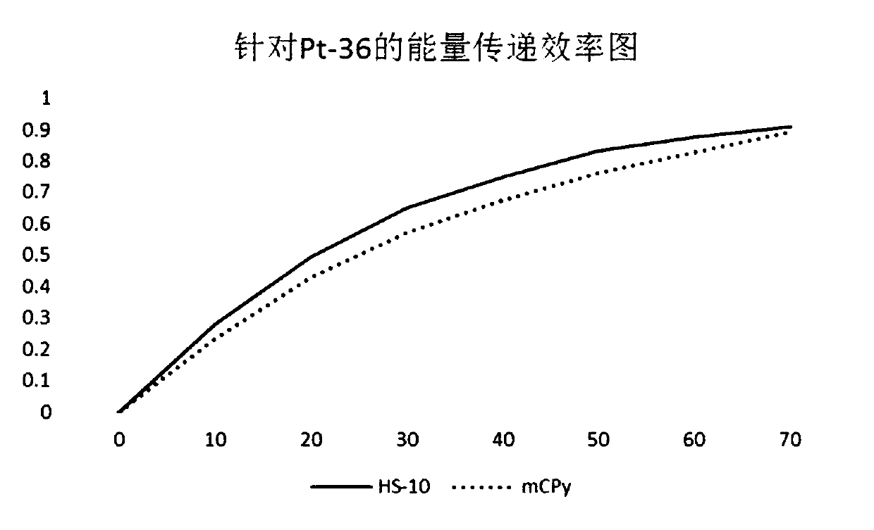
[0145] Pass the tetrahydrofuran solution through a 0.25 micron filter membrane and move it into a glove box filled with nitrogen. Pour nitrogen into the tetrahydrofuran solution and bubbling for 30 minutes to remove air. The host material HS-10 was dissolved in tetrahydrofuran after the above-mentioned treatment to prepare a 100 micromolar (100 μM) solution. Measure the intensity of the emission peak of the host material HS-10 at this concentration. The guest material Pt-36 of the same weight is weighed and added to the above solution in sequence so that the concentration of Pt-36 in the solution is 10 μM, 20 μM, 30 μM, 40 μM, 50 μM, 60 μM, 70 μM. Each time the concentration changes, measure the peak intensity of the host material at the corresponding concentration.

Embodiment 2

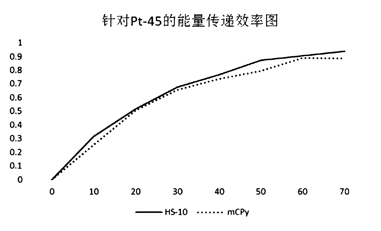
[0147] Pass the tetrahydrofuran solution through a 0.25 micron filter membrane and move it into a glove box filled with nitrogen. Pour nitrogen into the tetrahydrofuran solution and bubbling for 30 minutes to remove air. The host material HS-10 was dissolved in tetrahydrofuran after the above-mentioned treatment to prepare a 100 micromolar (100 μM) solution. Measure the intensity of the emission peak of the host material HS-10 at this concentration. The guest material Pt-45 of the same weight is weighed and added to the above solution in sequence so that the concentration of Pt-45 in the solution is 10 μM, 20 μM, 30 μM, 40 μM, 50 μM, 60 μM, 70 μM. Each time the concentration changes, measure the peak intensity of the host material at the corresponding concentration.


PUM


Abstract

The invention provides a luminous composition, which comprises at least one main body material and at least one object material, wherein the main body material has a structure shown as a general formula (I); the object material has a structure shown as a general formula (II); the formula (I) and the formula (II) are shown in the description; the main body material comprises a bridge connection triphenylamine plane capable of acting with the object material and a substitutional group forming a bowl-shaped structure with the plane, so that the mutual effect between the main body and the object can be achieved under the condition of avoiding the interference of other substances; the main body material has high triplet state energy stage; high energy transmission efficiency is shown between the main body and the object.

Description

【Technical Field】 [0001] The present invention relates to the field of organic electroluminescent materials, in particular to a luminescent composition, a luminescent layer and an electroluminescent device containing the luminescent composition. 【Background technique】 [0002] The use of organic materials to prepare various functional devices, especially for photoelectrically responsive functional devices, such as common organic electroluminescent devices, organic solar cell devices, organic field effect transistor devices and organic photosensitive sensor devices, has attracted more and more attention. . [0003] Organic electroluminescent materials (abbreviated as EL or OLED) refer to high molecular or small molecular organic materials that can emit light under the action of an electric field. Organic electroluminescent devices containing organic electroluminescent materials are a device technology that realizes electroluminescence by introducing one or more layers of organic fi...

Claims


Application Information

Patent Timeline
Patent Type & Authority Applications(China)
IPC IPC(8): C07D471/06C07D471/10C07D471/16C07D471/20C07D498/06C07D498/16C07F15/00C09K11/06H01L51/00H01L51/54H10K99/00
Inventor 黄达尤聪孙晓媛高琴
Owner AAC TECH NANJING
Learn More