Electroluminescent Device

a technology of electroluminescent device and electroluminescent layer, which is applied in the direction of luminescent composition, chemistry apparatus and processes, other domestic objects, etc., can solve the problems of complex formation of multiple polymer layers, poor performance, and conjugation between repeat units, so as to reduce or prevent the modulation of the first repeat unit's energy level, reduce or prevent the effect of triplet energy level and high triplet energy level

Inactive Publication Date: 2008-07-24
CDT OXFORD +1
View PDF18 Cites 12 Cited by
  • Summary
  • Abstract
  • Description
  • Claims
  • Application Information

AI Technical Summary

Benefits of technology

[0022]Conjugation of repeat units reduces the triplet energy level of the conjugated units as compared to the triplet energy of non-conjugated units. Therefore, in one embodiment the second repeat unit is at least partially non-conjugated in order to provide a break in conjugation along the polymer backbone and thereby reduce or prevent modulation of the first repeat unit's energy levels by conjugation. This is particularly preferred when the repeat unit of formula (I) possesses the desired energy level for use with a given metal complex, and / or when the metal complex has a high triplet energy level (such as green or blue phosphorescent materials).

Problems solved by technology

For both complexes, poor performance was observed.
In contrast, formation of multiple polymeric layers is complicated by the possibility of intermixing between layers when a polymeric material is deposited from solution onto a layer previously deposited from solution.
Another difficulty with using conjugated polymers, such as homopolyfluorene, as hosts is that conjugation between repeat units will reduce the HOMO-LUMO bandgap and reduce the energy level of the triplet excited state (as compared to the unconjugated monomer).
Although this might not be problematic for smaller bandgap complexes such as red emitting complexes, it does present difficulties for those metal complexes with wider bandgaps and higher triplet energies such as green and blue emitters.

Method used


Image

  • Electroluminescent Device
  • Electroluminescent Device
  • Electroluminescent Device

Examples


examples

[0096]General Procedure

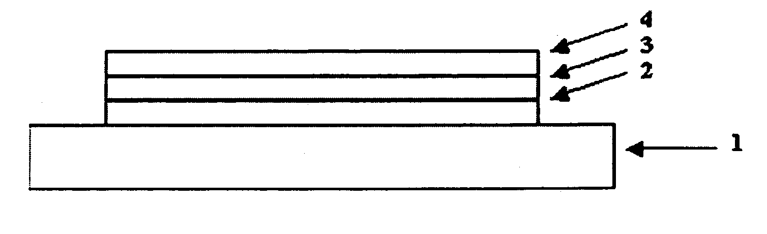
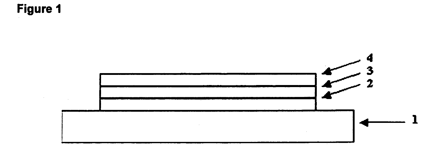
[0097]A green emitting complex 11 or red-emitting complex 12 (as disclosed in WO 02 / 66552) and a host polymer were deposited by spin coating from xylene solution onto a glass substrate comprising a layer of indium tin oxide, which may optionally be provided with a layer of hole injection material such as PEDT / PSS, or a hole transporting material. An electron transporting / hole blocking layer may optionally also be provided between the electroluminescent layer and the cathode. A bilayer cathode of calcium / aluminium was deposited over the electroluminescent layer and the device was encapsulated using an airtight metal enclosure available from Saes Getters SpA.

[0098]2,3,7,8,12,13,17,18-octaethyl-21H,23H-porphyrin platinum(II) may be used as an alternative to red emitting complex 12.

[0099]A bilayer cathod of lithium fluoride / aluminium may be used as an alternative to calcium / aluminium.

[0100]Devices were prepared using the following hosts:

[0101]Hosts A-E were used a...


PUM

PropertyMeasurementUnit
quantum efficiencyaaaaaaaaaa
electroluminescentaaaaaaaaaa

Abstract

An electroluminescent device comprising:—a first electrode for injection of positive charge carriers;—a second electrode for injection of negative charge carriers; and—an electroluminescent layer located between the first and second electrodes comprising a host material and a metal complex, wherein the host material comprises a polymer having a first repeat unit of formula (I): wherein each Ar is the same or different and independently represents an optionally substituted aryl or heteroaryl and any two Ar groups may be directly linked by a single bond.

Description

FIELD OF THE INVENTION[0001]The present invention relates to an electroluminescent device and an electroluminescent polymer therefor.BACKGROUND OF THE INVENTION[0002]One class of opto-electrical devices attracting increasing attention is that using a semiconducting organic material for light emission (an electroluminescent device) or as the active component of a photocell or photodetector (a “photovoltaic” device). The basic structure of these devices is a semiconducting organic layer sandwiched between a cathode for injecting or accepting negative charge carriers (electrons) and an anode for injecting or accepting positive charge carriers (holes) into the organic layer.[0003]In an organic light emitting device (OLED), electrons and holes are injected into the semiconducting organic layer where they combine to generate excitons that undergo radiative decay. Various classes of organic light emitting materials are known, in particular: polymers such as poly(p-phenylenevinylene) (as di...

Claims


Application Information

Patent Timeline
Patent Type & Authority Applications(United States)
IPC IPC(8): B32B9/04C08G73/00H01L51/00H01L51/30H01L51/50
CPCH01L51/0035H01L51/0039H01L51/5016H01L51/0059H01L51/0085H01L51/0043H10K85/111H10K85/115H10K85/151H10K85/631H10K85/342H10K50/11H10K2101/10C09K11/06Y10S428/917
Inventor TOWNS, CARLGRIZZI, ILARIAO'CONNOR, STEPHENSTEUDEL, ANNETTEPILLOW, JONATHANFRAMPTON, MICHAEL
Owner CDT OXFORD
Why Eureka
Try Eureka