
Automatic air pressure drainage kettle device for foundation pit and use method thereof

A technology for draining pots and kettles, applied in infrastructure engineering, construction, etc., which can solve problems such as messy cable layout and poor safety performance, and achieve the effects of improving automation, ensuring electricity safety, and reducing electric shocks

Active Publication Date: 2019-05-28
CHINA CONSTR THIRD ENG BUREAU GRP CO LTD
View PDF4 Cites 1 Cited by
  • Summary
  • Abstract
  • Description
  • Claims
  • Application Information

AI Technical Summary

Problems solved by technology

[0003] In order to overcome the technical defects such as messy cable layout and poor safety performance in the foundation pit drainage construction site in the prior art, the present invention provides an automatic air pressure drop drainage pot device for foundation pits and its use method, which can be used in construction sites and dewatering There are only air guide pipes and drainage pipes in the well, which avoids the safety problems caused by electric pumps entering the well and construction machinery operating errors on the site, and the electric wires are broken. The efficient management of the construction site solves the above technical problems

Method used


Image

  • Automatic air pressure drainage kettle device for foundation pit and use method thereof
  • Automatic air pressure drainage kettle device for foundation pit and use method thereof
  • Automatic air pressure drainage kettle device for foundation pit and use method thereof

Examples


Embodiment Construction

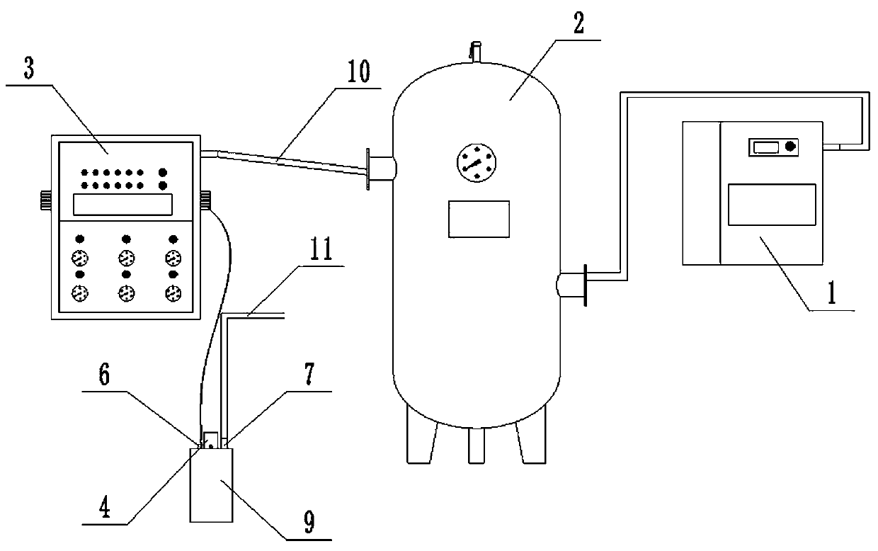
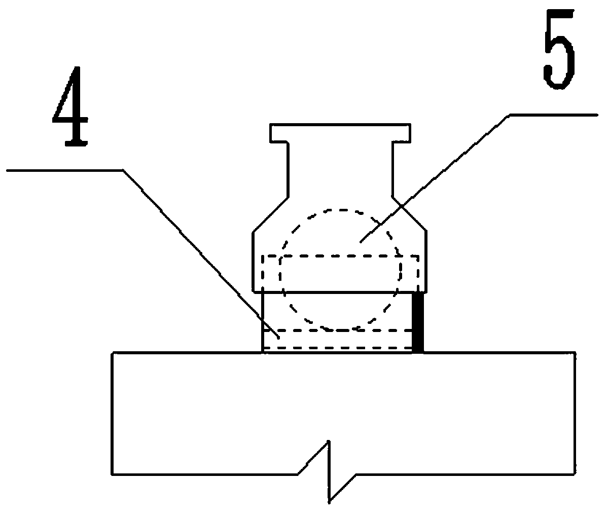
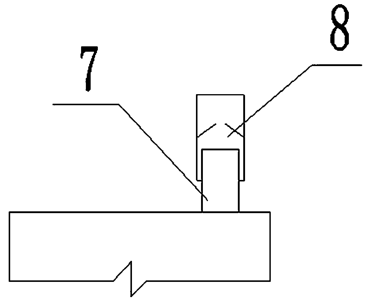
[0021] Such as figure 1 As shown, it is a schematic diagram of the overall structure of an automatic air pressure drop drainage pot device for a foundation pit according to the present invention, including an air compressor 1, an air storage tank 2, an air pressure control device 3, a water inlet 4, a floating ball plug 5, and an air inlet 6. Drain port 7, one-way drain valve 8, water collection and drainage pot 9, air guide pipe 10 and water guide pipe 11, connect air compressor 1, air storage tank 2, air pressure control device 3 and water collection and drainage pot 9 through air guide pipe 10 Together, the collection and drainage pot 9 is put into the dewatering well, and sinks through gravity and water intake, causing the floating ball plug 5 to float up and block the water inlet 4. The connection relationship between the water inlet 4 and the floating ball plug 5 is as follows: figure 2 As shown; the air pressure control device 3 presses the air into the collection and ...


PUM


Abstract

The invention discloses an automatic air pressure drainage kettle device for a foundation pit. The automatic air pressure drainage kettle device comprises an air compressor, an air storage tank, an air pressure control device, a floating bulb stopper, an air inlet, a water outlet, an one-way drainage valve, a drainage kettle, air guide pipes and a water guide pipe; wherein the air compressor, theair storage tank and the air pressure control device are successively connected in series through the air guide pipes; the air pressure control device is connected with the air inlet of the drainage kettle; a water inlet and the water outlet are formed at the upper end of the drainage kettle; the floating bulb stopper is installed in the water inlet; and the one-way drainage valve is installed atthe water outlet and connected with drainage equipment on the foundation pit ground through the water guide pipe. When the invention is in use, only the air guide pipes and the water guide pipe are available in a construction site and a foundation pit drainage well, thereby avoiding safety problems caused by an electric pump dropped into the well and on-site construction machinery incorrectly operated to break an electric wire; and the mutual cooperation between the air pressure control device with automatic adjustment function and the drainage kettle is utilized for realizing the efficient management to the construction site, thereby solving the technical problem.

Description

technical field [0001] The invention belongs to the technical field of foundation pit drainage construction, and in particular relates to an automatic air pressure drop drainage pot device for foundation pits and a method for using the same. Background technique [0002] With the development trend of the construction industry, the foundation pit of the building has also become larger and deeper, and the drainage of the foundation pit is also particularly important during the construction process. For the drainage of foundation pits, water pumps are the most commonly used at present, but there are problems such as power safety and low management efficiency in the process of pumping water. Contents of the invention [0003] In order to overcome the technical defects such as messy cable layout and poor safety performance in the foundation pit drainage construction site in the prior art, the present invention provides an automatic air pressure drop drainage pot device for foun...

Claims


Application Information

Patent Timeline
Patent Type & Authority Applications(China)
IPC IPC(8): E02D19/10
Inventor 余地华孔令宇杜永奎张宁宁雷增民刘振瑶
Owner CHINA CONSTR THIRD ENG BUREAU GRP CO LTD
Learn More