
Wave absorbing device for centrifugal machine model box

A centrifuge model and wave absorbing device technology, applied in the field of geotechnical engineering physical simulation test, can solve the problems of weak adaptability to water depth changes, very sensitive wave absorbing effect, incomplete wave absorbing, etc., so as to improve the test accuracy and ensure Accuracy and applicability

Active Publication Date: 2019-05-28
STATE GRID JIANGSU ECONOMIC RES INST +2
View PDF13 Cites 0 Cited by
  • Summary
  • Abstract
  • Description
  • Claims
  • Application Information

AI Technical Summary

Problems solved by technology

For the box-type energy dissipation structure, like the inclined plate with openings, there is the problem of incomplete wave dissipation, and there will still be strong reflected waves after the water wave flows through.
For the arc-shaped energy dissipation device, its wave dissipation effect is very sensitive to the height of the liquid level, and its adaptability to water depth changes is weak

Method used


Image

  • Wave absorbing device for centrifugal machine model box
  • Wave absorbing device for centrifugal machine model box
  • Wave absorbing device for centrifugal machine model box

Examples


Embodiment Construction

[0032] Further description will be made below in conjunction with the accompanying drawings and embodiments. The following examples are only used to illustrate the present invention and are not intended to limit the scope of the present invention. In addition, it should be understood that after reading the teachings of the present invention, those skilled in the art can make various changes or modifications to the present invention, and these equivalent forms also fall within the scope defined by the appended claims of the present application.

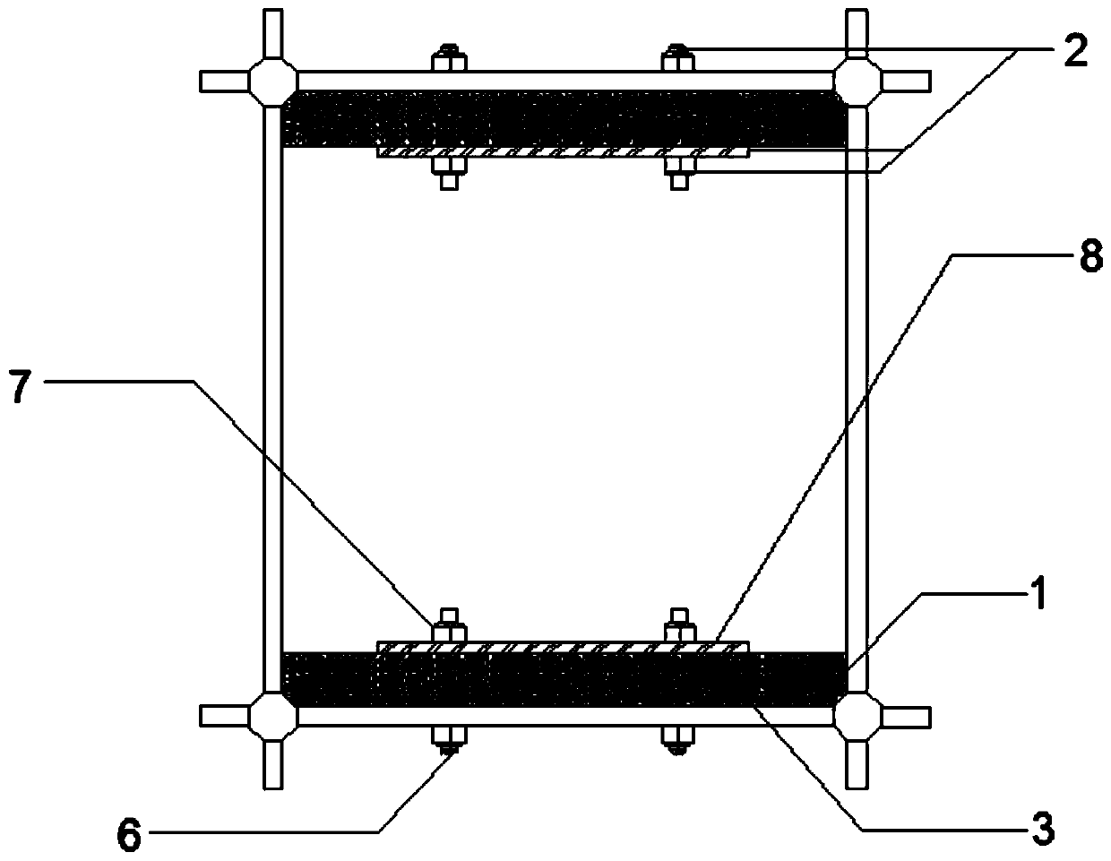
[0033] Such as figure 1 As shown, the specific implementation of the wave breaking device includes a wave breaking layer 1 with an "instant noodle" energy-dissipating structure, a rigid fixed structure 2 and a flexible adhesive layer 3. The wave breaking device is placed in the centrifuge model box and located on the water surface layer. The wave breaking layer 1 is fixed on the side wall of the centrifuge model box along the vibratio...


PUM


Abstract

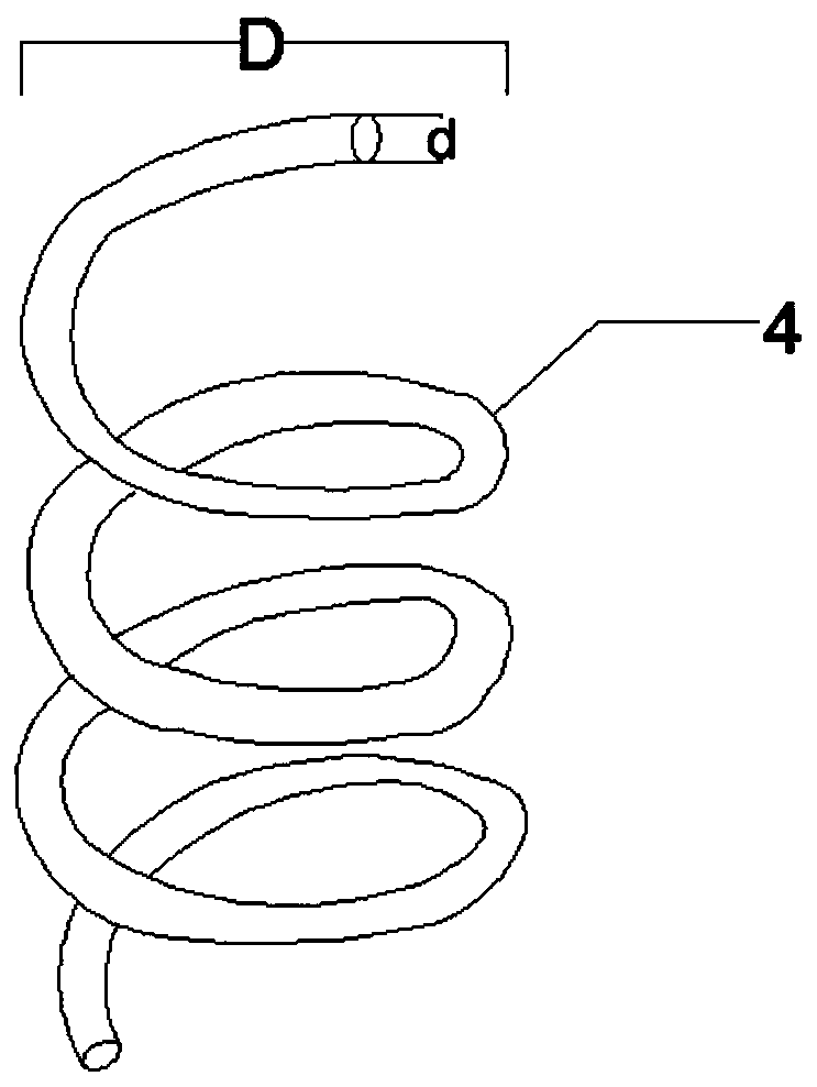
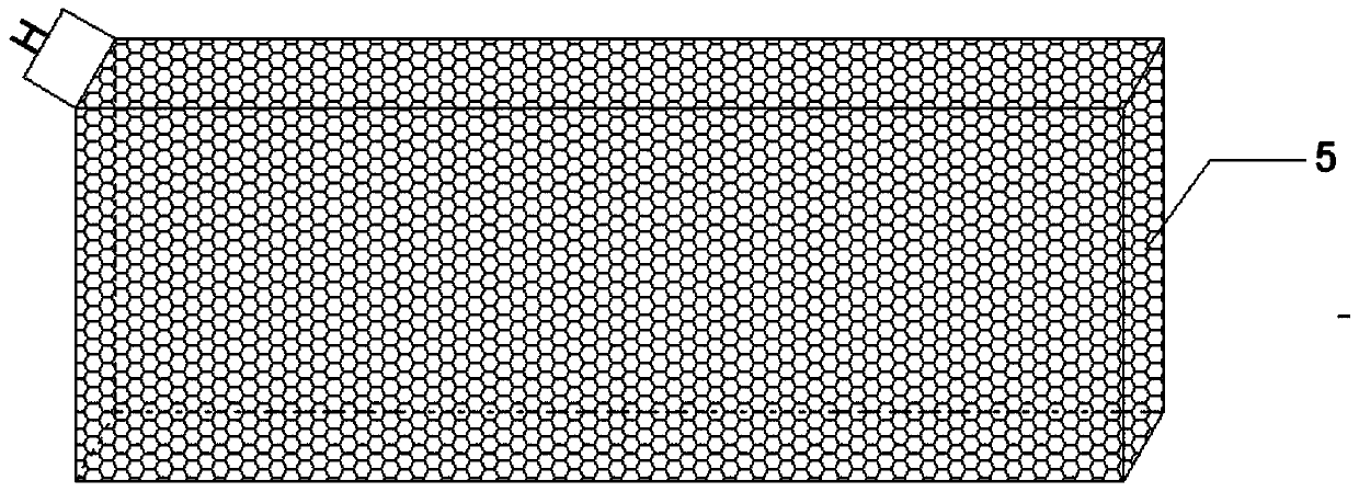
The invention discloses a wave absorbing device for a centrifuge model box. The wave absorbing device comprises a wave absorbing layer which is of an energy dissipation structure, the wave absorbing device is arranged in the centrifuge model box and located on the water surface layer, and the wave absorbing layer is fixed to the side wall of the centrifuge model box in the vibration direction through the rigid fixed structure and the flexible adhesive layer; the wave absorbing layer is of the instant noodle form structure formed by polymer filaments through winding, a basic energy dissipationunit of the wave absorbing layer is of a spiral structure formed by polymer filaments through hot working and winding in sequence, and countless spiral structures are connected or wound to form the instant noodle form structure; the rigid fixed structure comprises through bolts, nuts and a steel sheet with through screw holes. According to the wave absorbing device, wave absorbing for water wavesand isolation for a soil body are achieved simultaneously, the applicability of the device on the basis of testing original equipment is increased, the applicability is very high, and the device can be used in an experiment of a high gravity centrifuge.

Description

technical field [0001] The invention relates to the field of geotechnical engineering physical simulation tests, in particular to a wave elimination device for a centrifuge model box. Background technique [0002] Earthquake simulation shaking table is an important test equipment for seismic research, and has been widely used in earthquake engineering research at home and abroad. The shaking table test is a test method that can truly reproduce the response of the soil layer or structure and the earthquake in the laboratory. It can reproduce the whole process of earthquake action or artificial action in real time. The development of the shaking table is to study the seismic response of the soil layer or structure. effective means are provided. Earthquake simulation shaking table test is a real earthquake simulation test. Various forms of seismic waves can be truly reproduced on the table, and the damage mechanism of soil layers and structures under earthquake action can also...

Claims


Application Information

Patent Timeline
IPC IPC(8): G01M7/02
Inventor 丁志锋韩超周燕国王越彭千陈勇刘寅莹
Owner STATE GRID JIANGSU ECONOMIC RES INST
Learn More