Device and method for monitoring and displaying state of power equipment

A technology for power equipment and state monitoring, applied in the direction of circuit devices, power network operating system integration, electrical components, etc., can solve the problems of increased state visualization effects, limited state monitoring means, and inability to manage power equipment, etc., to achieve increased state visualization effects , Enhance the effect of management and monitoring

Inactive Publication Date: 2019-05-28
ANHUI KAICHUAN POWER PROTECTION EQUIP
View PDF8 Cites 6 Cited by
  • Summary
  • Abstract
  • Description
  • Claims
  • Application Information

AI Technical Summary

Problems solved by technology

[0004] The purpose of the present invention is to overcome the deficiencies of the prior art, provide a device and method for monitoring and displaying the state of electric equipment, and solve the problem that the state monitoring means of traditional electric equipment are limited and cannot effectively manage each electric equipment. ...

Method used


Image

  • Device and method for monitoring and displaying state of power equipment
  • Device and method for monitoring and displaying state of power equipment

Examples


Embodiment 1

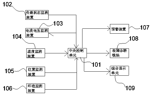
[0034] A device for monitoring and displaying the status of electric equipment, please refer to the attached figure 1 shown, including:

[0035] A monitoring unit, the monitoring unit includes a temperature monitoring device 104, a current and voltage monitoring device 103, a position monitoring device 105, an environment monitoring device 106 and a load status monitoring device 102, the monitoring unit is used to obtain and record the operating status parameters of the power equipment at different times ;

[0036] The early warning device 107, the early warning device 107 includes a trend prediction module and an alarm module, and the trend prediction module is used to generate the operation trend of the next moment according to the acquired power equipment operation state parameters, and compare it with the monitoring threshold according to the direction of the trend; The module is used to give an alarm when the trend exceeds the monitoring threshold or the current operatin...

Embodiment 2

[0043] A method for monitoring and displaying the status of electric equipment, please refer to the attached figure 2 As shown, the method includes:

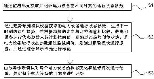
[0044] S1. Obtain and record the operating state parameters of the electric equipment at different times through the monitoring unit;

[0045] S2. Through the trend prediction module, according to the acquired operating state parameters of the power equipment, generate the operating trend at the next moment, and compare it with the monitoring threshold according to the direction of the trend. If the operating state parameters of the electric equipment do not exceed the monitoring threshold, skip In the trend prediction state, if the operating state parameters of the power equipment exceed the monitoring threshold, an alarm will be issued through the alarm module and marked through the integrated display unit;

[0046] S3. The fault diagnosis module records the state change and maintenance situation of each electric device, and...


PUM


Abstract

The invention discloses a device for monitoring and displaying the state of power equipment. The device comprises a monitoring unit, an early warning device, a fault diagnosis module, a comprehensivedisplay unit and a central control unit, wherein the early warning device comprises a trend prediction module and an alarm module, and the trend prediction module is used for generating the operationtrend of the next moment according to the obtained operation state parameters of the power equipment and comparing the operation trend with a monitoring threshold value according to the trend; the alarm module is used for giving an alarm when the trend exceeds a monitoring threshold value or the current operation state parameter exceeds the monitoring threshold value; and the central control unitis used for performing state monitoring, state change prediction, real-time state display and fault grading on the power equipment. By establishing a 3D model for each piece of power equipment and displaying the operation state parameters of each piece of power equipment in real time, the state visualization effect of the power equipment is improved, reliability grading is carried out on all powerequipment, and the management monitoring effect of the power equipment is enhanced.

Description

technical field [0001] The invention relates to the technical field of electric equipment, in particular to a device and method for monitoring and displaying the state of electric equipment. Background technique [0002] In the long-term operation of the power grid system, it is inevitable that the performance will gradually decline, the reliability will decrease, and the failure rate will increase, which will endanger the safe operation of the system. Therefore, the operating status of the power grid system must be monitored. [0003] However, due to the limitations of management, technology and many other factors in the data source of the existing condition monitoring, there is no way to obtain first-hand information in terms of data fusion, and the data interaction with dispatching and relay protection is often done through automation. The quasi-real-time data of the system mapping interface evaluates the equipment with problems according to the management guidelines, and...

Claims


Application Information

Patent Timeline
IPC IPC(8): H02J13/00G08B21/18
CPCY04S10/40Y04S20/242Y02B70/30
Inventor 冯四阳汤学生李俊吴雷
Owner ANHUI KAICHUAN POWER PROTECTION EQUIP
Why Eureka
Try Eureka