Welding method and system

A welding method and control system technology, applied in welding equipment, welding equipment, auxiliary welding equipment, etc., can solve the problems of mutual influence and interference between welding wire and welding parts, so as to improve control effect, ensure stability and avoid interference Effect

Pending Publication Date: 2019-05-31
徐小华
View PDF7 Cites 3 Cited by
  • Summary
  • Abstract
  • Description
  • Claims
  • Application Information

AI Technical Summary

Problems solved by technology

[0005] The purpose of the present invention is to provide a welding method and system to solve the problem that the welding wire and the weldment will affect each other and interfere with each other during the welding process of the existing cage-like, mesh-like, and steel bar-like structures. The purpose of avoiding mutual influence and preventing interference

Method used


Image

  • Welding method and system
  • Welding method and system
  • Welding method and system

Examples


Embodiment 1

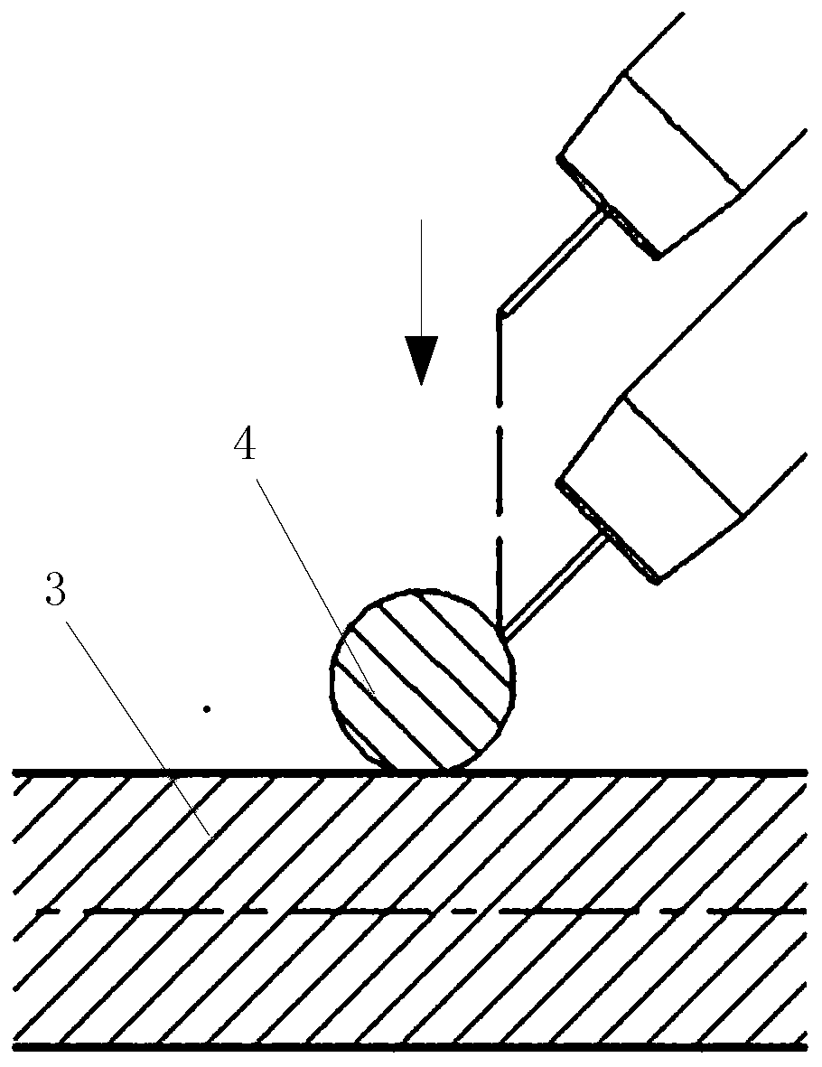
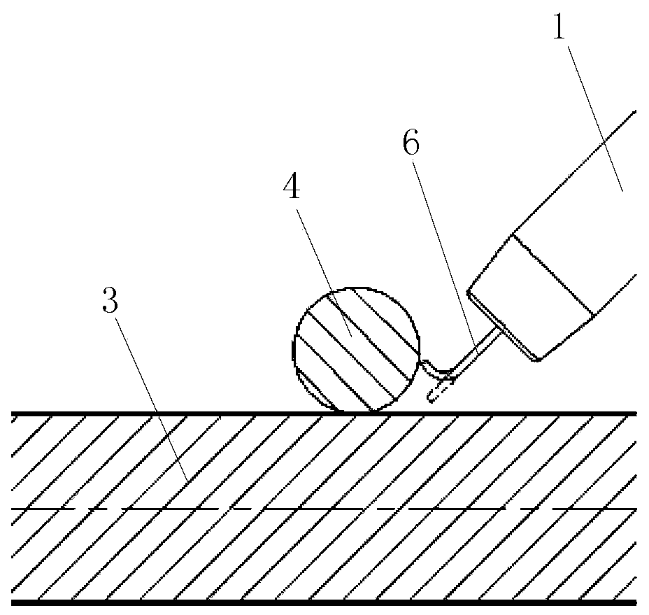
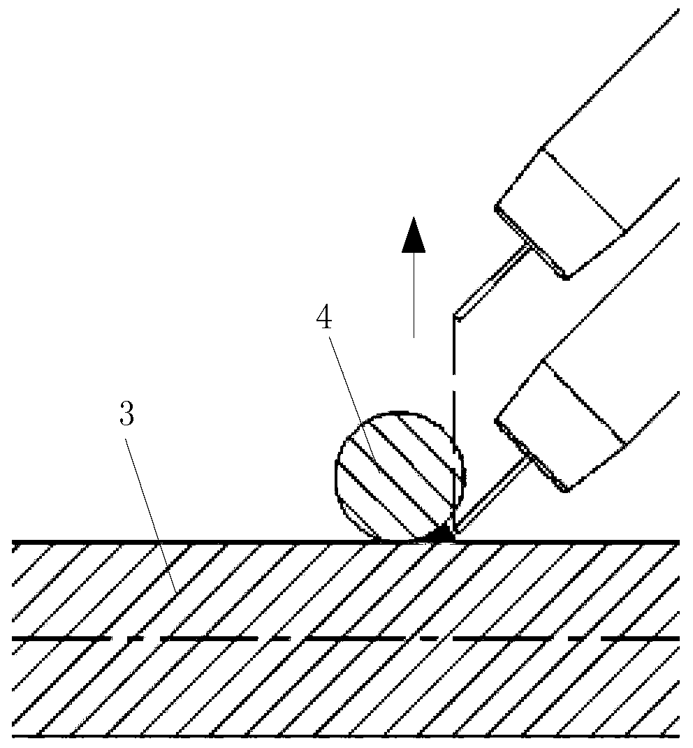
[0040] A welding method, using a welding torch to weld the first weldment and the second weldment, and at any time before starting welding, the welding wire is retracted in a direction away from the welding spot between the first weldment and the second weldment. The welding wire is retracted to a position where the welding wire does not contact the first weldment and the second weldment when the welding wire moves towards the welding spot.

[0041] This embodiment is applicable to the welding of the main reinforcement and the winding reinforcement during the automatic welding process of the reinforcement cage. The reinforcement cage is output and formed by the wire coiling machine. During the whole welding process, the reinforcement cage is in the process of continuous advancement and rotation, which can avoid the interference of the winding wire on the welding wire. Among them, weldment one 3 is the main rib, and weldment two 4 is the winding rib.

[0042] In addition to th...

Embodiment 2

[0045] A welding method, on the basis of Embodiment 1, further includes a wire feeding motor, the wire feeding motor is used to output the welding wire in the forward rotation during the welding process; the wire feeding motor is controlled to reverse by the wire withdrawal control system to realize the return of the welding wire retreat.

[0046] Including the external power supply VCC2, also including the wire feeder power supply VCC1 matched with the wire feeder motor;

[0047] Such as Figure 5 as shown, Figure 5 The dotted line in the middle represents the wire withdrawal control system:

[0048] When the wire withdrawal control system controls the power supply of the wire feeder to supply power for the wire feeder, that is, when K3 and K4 are closed and K1 and K2 are cut off, the wire feeder motor rotates forward;

[0049] When the wire withdrawal control system controls the external power supply to supply power to the wire feeding motor, that is, when K1 and K2 are ...

Embodiment 3

[0051] A welding method, on the basis of embodiment 1, comprising a wire feeder power supply VCC1 matched with the wire feeder motor;

[0052] Such as Figure 6 as shown, Figure 6 The dotted line in the middle represents the wire withdrawal control system. The wire withdrawal control system is used to control the power supply direction of the wire feeder power supply to the wire feed motor:

[0053] When the wire withdrawal control system controls the power supply of the wire feeder to supply power for the wire feeder, that is, when K3 and K4 are closed and K1 and K2 are cut off, the wire feeder motor rotates forward;

[0054] When the wire withdrawal control system controls the external power supply to supply power to the wire feeding motor, that is, when K1 and K2 are closed and K3 and K4 are cut off, the wire feeding motor reverses.


PUM


Abstract

The invention discloses a welding method and system. A first welding piece and a second welding piece are welded by a welding torch, and at any time before welding is started, a welding wire retractsback in the direction away from a welding point between the first welding piece and the second welding piece. The aim is to provide the welding method and system for solving the problems that in the welding process of a crossed contact point of an existing mesh workpiece, a welding wire and welding pieces influence each other and interference happens, and the aims of avoiding mutual influences andpreventing interference are achieved. After wire retreating, the condition that the welding torch moves, consequently the welding wire at the tail end of an electric conduction nozzle interferes thewelding pieces is avoided, the welding wire at the tail end of the electric conduction nozzle is in the normal shape, the welding quality and the welding stability are ensured, stable arcing is ensured, and meanwhile, the problems of workpiece welding penetration or notch generation caused by the fact that the length of the welding wire cannot be accurately controlled are solved.

Description

technical field [0001] The invention relates to the field of welding, in particular to a welding method and system. Background technique [0002] With the rapid development of domestic road and bridge construction, steel cages are more and more commonly used in pile foundation construction. The production of traditional steel cages is mostly made by hand, which has high labor intensity, low production efficiency and high cost; or it is made by traditional equipment, and the traditional steel cage production equipment has a low degree of automation, although the production efficiency is higher than that of manual production. , but the welding of welding piece 1 and welding piece 2 still adopts manual welding. The welding quality and speed depend on the welding technology and speed of workers. The irregular shape of solder joints and unstable quality directly affect the production efficiency and quality of the steel cage. In order to reduce manpower consumption and cost, wire...

Claims


Application Information

Patent Timeline
Patent Type & Authority Applications(China)
IPC IPC(8): B23K31/02B23K31/12B23K37/02
Inventor 徐小华向光明
Owner 徐小华
Why Eureka
Try Eureka