Eureka AIR delivers breakthrough ideas for toughest innovation challenges, trusted by R&D personnel around the world.

Anti-theft door frame processing assembly clamping mechanism and its clamping method

A technology of clamping mechanism and anti-theft door, which is applied in the direction of workpiece clamping device, metal processing equipment, manufacturing tools, etc., can solve the problems of time-consuming and labor-intensive

Active Publication Date: 2020-09-01
YONGKANG JIEDICI ROBOT TECH CO LTD
View PDF11 Cites 0 Cited by
  • Summary
  • Abstract
  • Description
  • Claims
  • Application Information

AI Technical Summary

Problems solved by technology

[0003] Before assembling the anti-theft door frame, it is necessary to fix the four assembly parts of the anti-theft door frame. The traditional fixing method is to manually align and cut the assembly parts of the anti-theft door frame, and then by Soldering assembly, which is time-consuming and labor-intensive to operate

Method used


Image

  • Anti-theft door frame processing assembly clamping mechanism and its clamping method
  • Anti-theft door frame processing assembly clamping mechanism and its clamping method
  • Anti-theft door frame processing assembly clamping mechanism and its clamping method

Examples


Embodiment Construction

[0034] The following will clearly and completely describe the technical solutions in the embodiments of the present invention with reference to the accompanying drawings in the embodiments of the present invention. Obviously, the described embodiments are only some, not all, embodiments of the present invention. Based on the embodiments of the present invention, all other embodiments obtained by persons of ordinary skill in the art without creative efforts fall within the protection scope of the present invention.

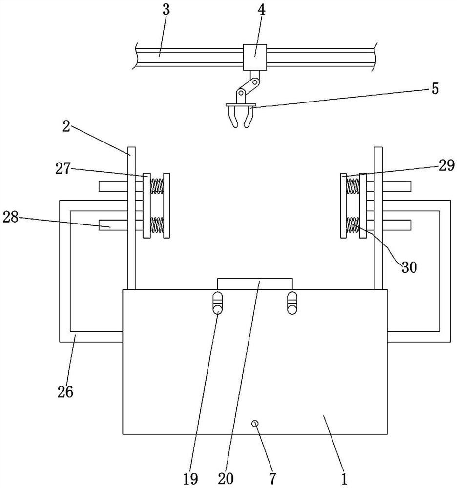
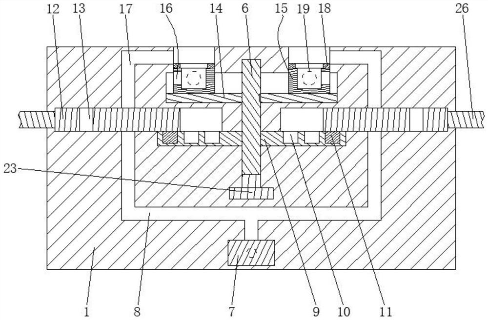
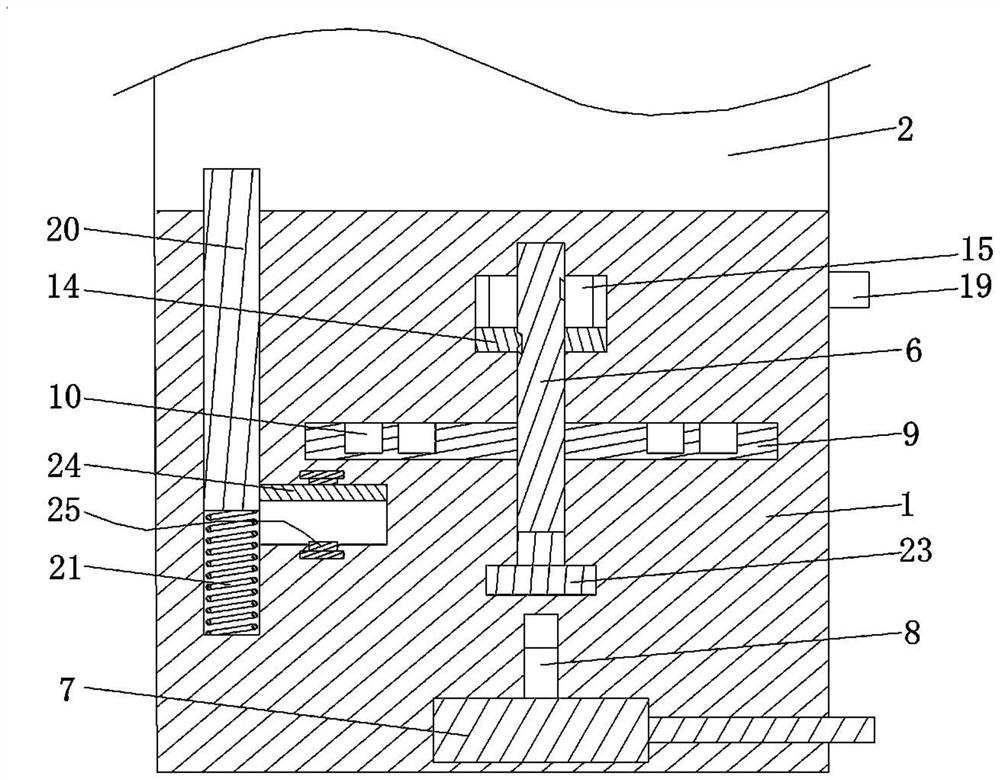
[0035] Such as Figure 1-8 as shown, figure 1 It is a schematic front view of the structure of the present invention; figure 2 It is a front sectional view of the inner structure of the fixed bottom block of the present invention; image 3 It is a left side sectional view of the inner structure of the fixed bottom block and the support block structure of the present invention; Figure 4 It is a schematic top view of the structure of the turntable and the transm...


PUM


Abstract

The invention provides a security door frame processing assembly clamping mechanism comprising a fixed bottom block. A transmission shaft is connected into the fixed bottom block; a sleeve block is further included, the sleeve block can move up and down along the transmission shaft, negative pressure cylinders are fixed to the two ends of the sleeve block, and the negative pressure cylinders are provided with third air passages; a negative pressure pump and a total air passage are also included, one end of the total air passage communicates with a suction port of the negative pressure pump, and the third air passages communicate with the other end of the total air passage in the up and down movement process of the negative pressure cylinders; a stepping motor, an abutting plate, a pressingplate, a first spring and two pressing switches are further included, the stepping motor is connected with the transmission shaft, the output ends of the pressing switches are in signal connection with the input end of the stepping motor through a single chip microcomputer, the abutting plate is slidably connected to the interior of the fixed bottom block up and down, the upper end of the abutting plate extends out of the fixed bottom block, and the two ends of the first spring are connected with the fixed bottom block and the abutting plate; and two side clamping plates and a driving part capable of driving the two side clamping plates to move face to face and back to back are further included. The clamping mechanism can replace manual work and can save time and labor.

Description

technical field [0001] The invention relates to the technical field of door frame clamping, in particular to an anti-theft door frame processing assembly clamping mechanism and a clamping method thereof. Background technique [0002] With the improvement of people's safety awareness, various anti-theft devices have entered thousands of households. Especially in recent years people's income continues to increase, and various valuables in the family have also increased, and family security has become a problem that people generally care about. In the selection of anti-theft equipment, security doors have become people's first choice. [0003] Before assembling the anti-theft door frame, it is necessary to fix the four assembly parts of the anti-theft door frame. The traditional fixing method is to manually align and cut the assembly parts of the anti-theft door frame, and then by Welding assembly, its operation is time-consuming and laborious. [0004] Therefore, how to make...

Claims


Application Information

Patent Timeline
Patent Type & Authority Patents(China)
IPC IPC(8): B25B11/00B23K37/04
Inventor 应振涛应志敏
Owner YONGKANG JIEDICI ROBOT TECH CO LTD
Why Eureka
Eureka Blog
Learn More