Auxiliary clamping device for airtightness detection of liquid cooling module

A technology of air tightness detection and clamping device, which is applied in the direction of using liquid/vacuum degree for liquid tightness measurement, sleeve/socket connection, pipe/pipe joint/pipe fitting, etc., which can solve the detection time lag and the time-consuming workpiece clamping. Effortless, unable to meet the use requirements and other problems

Pending Publication Date: 2021-11-05
10TH RES INST OF CETC
View PDF0 Cites 0 Cited by
  • Summary
  • Abstract
  • Description
  • Claims
  • Application Information

AI Technical Summary

Problems solved by technology

Most of the clamping of air tightness test specimens is manual clamping, which is time-consuming and labor-intensive; some areas are difficult to operate manually due to space constraints
The size of various liquid cooling modules is not universal, and cannot be set according to different products. The universality is poor, and it cannot meet the requirements of use, which increases the cost to a certain extent.
In response to this situation, different airtight detection auxiliary clamping devices are currently designed for specific products, which wastes resources and at the same time the detection efficiency is low. Often, the clamping device is designed after the product comes out, resulting in a delay in detection time and a delay in the construction period.

Method used


Image

  • Auxiliary clamping device for airtightness detection of liquid cooling module
  • Auxiliary clamping device for airtightness detection of liquid cooling module
  • Auxiliary clamping device for airtightness detection of liquid cooling module

Examples


Embodiment Construction

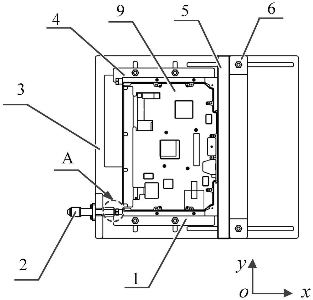
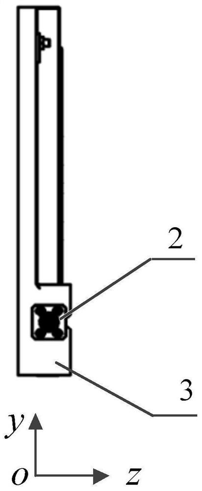
[0016] refer to Figure 1-Figure 3 . In the preferred embodiment described below, an auxiliary clamping device for airtight testing of a liquid-cooled module includes: a strip-shaped positioning bar 5 fixed on the seat plate 3 to clamp the liquid-cooled module 9 to be tested, characterized in that: The two sides of the positioning bar 5 are provided with the first mobile lock bar 1 and the second mobile lock bar 4 fixedly connected to the slide rails. The chute of the slide rail slides into the clamping area of ​​the door-shaped angle plate formed symmetrically in the x direction, and is fixed on the bar-shaped positioning bar 5 by sliding adjustment through the screws on the two parallel angle plate chutes; the clamping is on the first The liquid cooling module 9 to be tested between the moving lock bar 1 and the second moving lock bar 4 slides towards each other, forming a clamping area with the x-direction positioning bar 5, and the detection head 2 is fixed on the seat th...


PUM


Abstract

An auxiliary clamping device for airtightness detection of the liquid cooling module disclosed by the invention is simple and practical in structure and high in universality. According to the technical scheme, a strip-shaped positioning strip, a movable x-direction locking strip and a y-direction movable locking strip, namely a first movable locking strip and a second movable locking strip which are fixedly connected to a sliding rail, are arranged on a base plate, after a to-be-detected liquid cooling module is placed on an upper bottom plate, the z-direction position of a detection head is adjusted, the liquid cooling module is inserted into a detection connector, the x-direction positioning strip, the first movable locking strip and the second movable locking strip are adjusted at the same time, the clamped and fixed to-be-detected liquid cooling module slides in the y direction along the base plate through the y-direction sliding groove, meanwhile, the position in the y direction is locked through the locking screw, direction positioning of different y-direction sizes is achieved, and the to-be-detected liquid cooling module pushes the strip-shaped positioning strip to slide in the x direction along the base plate. The back-to-back coupling connection with the x-direction locking strip is achieved, and the x-direction locking strip moves along the C-shaped sliding groove of the base plate through a sliding bolt on the x-direction locking strip and is fixed to the base plate.

Description

technical field [0001] The invention relates to the technical field of airtight detection of liquid cooling modules, in particular to an auxiliary clamping device for universal airtight detection of liquid cooling modules. Background technique [0002] As the communication and electronic equipment functions in the aerospace field become more and more powerful, and the power of the equipment is also increasing, the traditional heat dissipation system can no longer meet the heat dissipation requirements of the equipment. To achieve high-efficiency conduction heat dissipation and meet the requirements of equipment environment adaptation. As an important part of the heat dissipation system, the liquid cooling component has air tightness and pressure resistance performance as its key indicators. If a liquid cooling leak occurs, it will cause equipment pollution or even a short circuit. Therefore, the air tightness test of the liquid cooling component very important. However, th...

Claims


Application Information

Patent Timeline
Patent Type & Authority Applications(China)
IPC IPC(8): G01M3/02F16L21/035
CPCG01M3/02F16L21/035
Inventor 王云陶亚平雷涛
Owner 10TH RES INST OF CETC
Why Eureka
Try Eureka