Electronic information screen based on infrared ray control

An electronic information and infrared technology, applied in the field of information screens, can solve the problems of lack of anti-collision function, reduced function of convex mirror, and obstruction of light transmission, etc., to achieve true and reliable displayed information, reduce traffic accidents, and strong penetrating power Effect

Pending Publication Date: 2019-05-31
SHANGQIU NORMAL UNIVERSITY
View PDF2 Cites 6 Cited by
  • Summary
  • Abstract
  • Description
  • Claims
  • Application Information

AI Technical Summary

Problems solved by technology

[0002] In order for car drivers to clearly observe the information of vehicles on the road and reduce the occurrence of traffic accidents, convex mirrors are usually installed at road intersections and complex mountain roads to expand the driver's field of vision and detect curves or vehicles on the opposite side of the intersection early. , in order to reduce the occurrence of traffic accidents, but in extreme weather such as rain, snow, fog, etc., due to the obstruction of light transmission, the function of the convex mirror is reduced, resulting in the collision of passing vehicles, causing traffic accidents, and even causing vehicle collisions on mountain roads. out of the road and fall off the cliff, causing huge losses to people's lives and property. Therefore, it is becoming more and more difficult to use convex mirrors to meet the increasingly complex road traffic, and the poles used to support the convex mirrors lack anti-collision functions, and traffic accidents occur. When the accident occurs, the vehicle cannot be cushioned

Method used


Image

  • Electronic information screen based on infrared ray control
  • Electronic information screen based on infrared ray control
  • Electronic information screen based on infrared ray control

Examples


Embodiment Construction

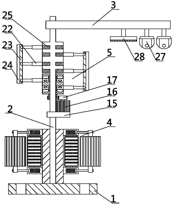
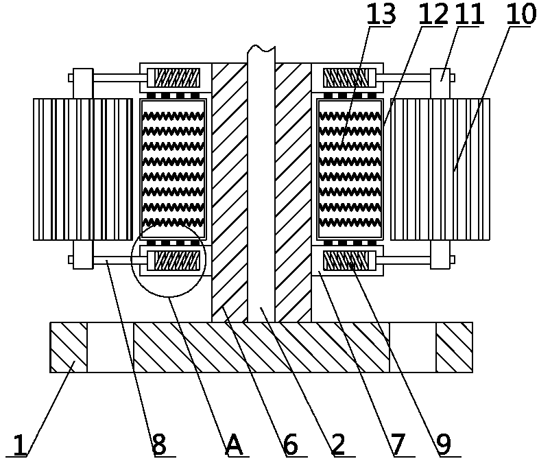
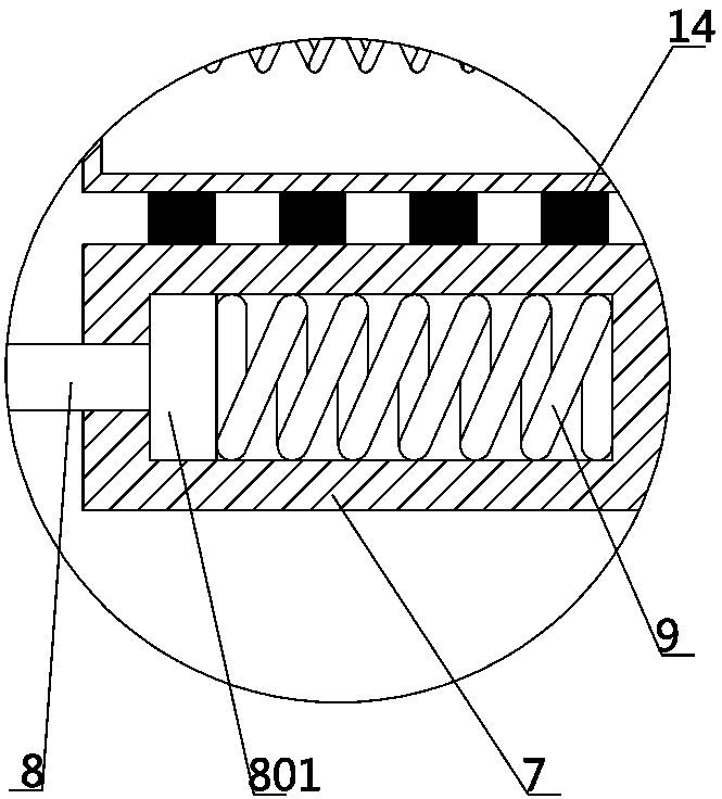
[0020] Such as Figure 1-8 As shown, the specific embodiment of the present invention adopts the following technical solutions: an electronic information screen based on infrared control, including a base 1, a pole 2, an anti-collision device 4 and an information display device 5, and the upper middle part of the base 1 is connected to the support The lower end of the pole 2 is fixedly connected, and the pole 2 is provided with an anti-collision device 4 and an information display device 5 sequentially from bottom to top. A camera 27 and an infrared induction disc 28; the pole 2 is fixedly connected with the protective tube 6 of the anti-collision device 4, and the upper and lower sides of the protective tube 6 are fixedly connected with four annularly distributed sliding tubes 7, and between the sliding tubes 7 The side portion of the protective tube 6 in between is provided with an annular buffer box 12, the upper and lower sides of the buffer box 12 are fixedly connected to...


PUM


Abstract

The invention discloses an electronic information screen based on infrared ray control. The electronic information screen comprises a base, a supporting rod, an anti-collision device and an information display device. The base is fixedly connected with the supporting rod. The supporting rod is provided with the anti-collision device and the information display device from bottom to top. The supporting rod is fixedly connected with a transverse rod. A camera and an infrared sensing plate are fixedly connected with the transverse rod. The anti-collision device comprises a protection cylinder, abuffering box and a buffering roller. A display screen of the information display device is fixed to a fixed plate. The fixed plate is connected with a rotating cylinder through a telescopic rod. Therotating cylinder is in transmission connection with a steering engine. At the corner of a road, the display screen displays vehicle information shot by the camera, meanwhile on the basis of the vehicle position information measured by an infrared sensor on the infrared sensing plate, the steering engine rotates, the telescopic rod stretches out and draws back, the direction and angle of the display screen are adjusted, a vehicle driver can conveniently observe the corner information of the vehicle, and vehicle accidents are reduced; in addition, due to the three-stage protection function of the anti-collision device, the vehicle can be prevented from directly rushing out of the road, and the loss caused by the vehicle accidents is reduced.

Description

technical field [0001] The invention belongs to the technical field of information screens, in particular to an electronic information screen based on infrared control. Background technique [0002] In order for car drivers to clearly observe the information of vehicles on the road and reduce the occurrence of traffic accidents, convex mirrors are usually installed at road intersections and complex mountain roads to expand the driver's field of vision and detect curves or vehicles on the opposite side of the intersection early. , in order to reduce the occurrence of traffic accidents, but in extreme weather such as rain, snow, fog, etc., due to the obstruction of light transmission, the function of the convex mirror is reduced, resulting in the collision of passing vehicles, causing traffic accidents, and even causing vehicle collisions on mountain roads. out of the road and fall off the cliff, causing huge losses to people's lives and property. Therefore, it is becoming mor...

Claims


Application Information

Patent Timeline
Patent Type & Authority Applications(China)
IPC IPC(8): E01F9/608E01F15/00G09F9/00G08C23/04
Inventor 李媛朱芳王沙沙孙春志
Owner SHANGQIU NORMAL UNIVERSITY
Why Eureka
Try Eureka