
Liquid nitrogen freezing device with freezing pipe provided with partition plate and construction method

A technology of freezing tubes and freezers, which is applied in basic structure engineering, soil protection, construction, etc., and can solve the problems that the development of frozen soil cannot be accurately controlled, the control is difficult, and the uniformity of the frozen wall is poor.

Active Publication Date: 2019-05-31
CHINA UNIV OF MINING & TECH
View PDF2 Cites 3 Cited by
  • Summary
  • Abstract
  • Description
  • Claims
  • Application Information

AI Technical Summary

Problems solved by technology

Due to the small size of the liquid supply pipe inside the freezing pipe, the position inside the freezing pipe cannot be accurately controlled, so it is difficult to control the distribution of liquid nitrogen inside the freezing pipe and the gasification process, and the development of the frozen soil around the freezing pipe cannot be precisely controlled, resulting in liquid The uniformity of the frozen wall formed by nitrogen freezing is poor

Method used


Image

  • Liquid nitrogen freezing device with freezing pipe provided with partition plate and construction method
  • Liquid nitrogen freezing device with freezing pipe provided with partition plate and construction method
  • Liquid nitrogen freezing device with freezing pipe provided with partition plate and construction method

Examples


specific Embodiment

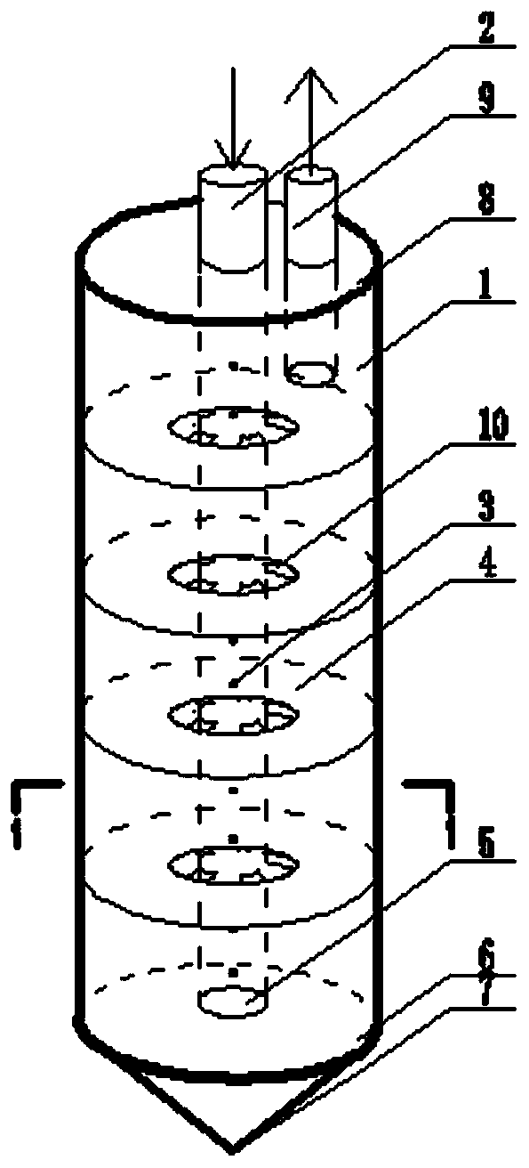
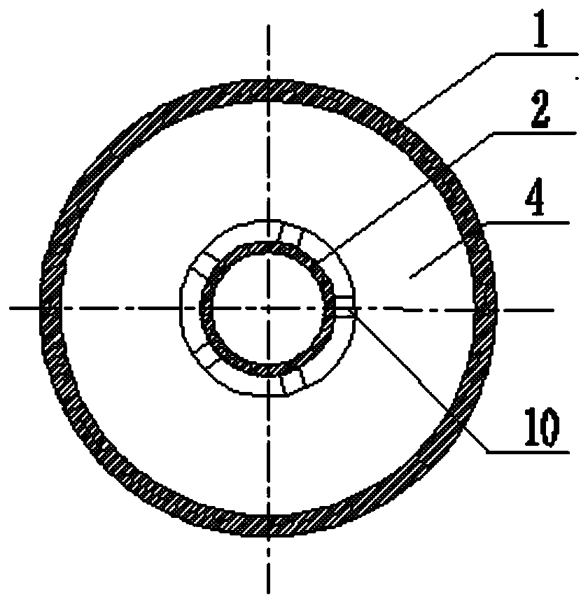
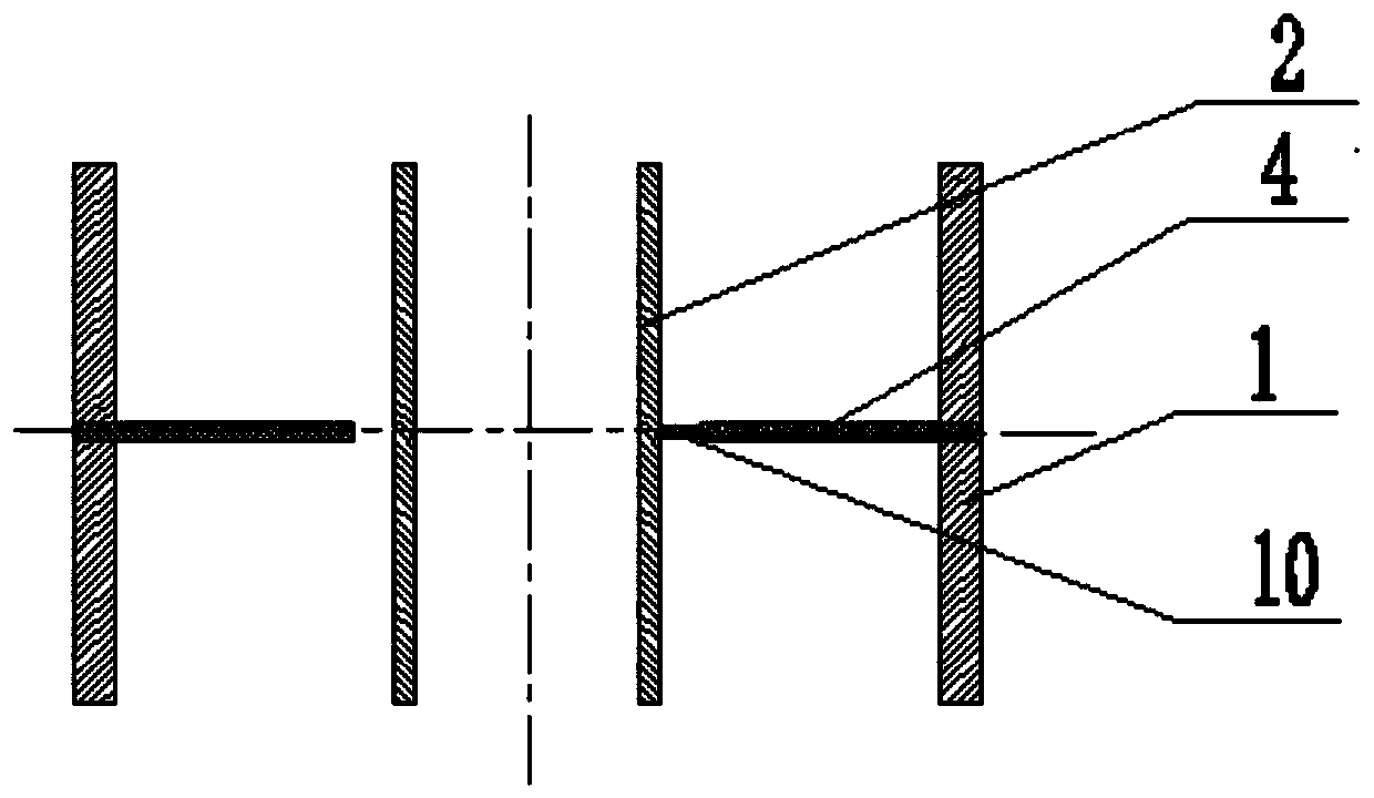
[0033] The first step is to measure the depth range of the bottom layer that needs to be frozen according to the needs of actual construction. According to the measurement situation, open spray holes 3 along the direction of the freezing pipe 1 where holes need to be opened. Five spring supports 10 are welded at the inner edge of the plate, and the upper and lower sides of the circular dividing plate 4 are welded with the freezing tubes 1 at both ends to form the joints where the dividing plate is in the middle and freezing the tubes 1 on both sides. According to the needs of freezing depth during construction, joints with partitions are welded at different positions of the freezing tube 1 to form liquid nitrogen freezing tubes 1 with different partition intervals;

[0034] In the second step, use the plugging 5 to block one end of the liquid supply pipe, and insert the liquid supply pipe along the spring support 10 on the dividing plate into the freezing pipe with the end that...


PUM


Abstract

The invention discloses a liquid nitrogen freezing device with a freezing pipe provided with partition plates and a construction method. According to construction adopting a quick rescuing freezing method, soil masses of the freezing section are subjected to water shutoff and reinforcing for using. The freezing device is composed of a joint of the freezing pipe, a liquid supplying pipe and a gas exhausting pipe, the joint of the freezing pipe is composed of a two freezing pipe sections and annular partition plate through welding, deformable elastic supporting bases are arranged on the inner edge of the partition plate at intervals, and it is ensured that the liquid supplying pipe is located in the center of the freezing pipe. Liquid spraying holes are formed in the portions, within a section range needing freezing, of the liquid supplying pipe, sprayed liquid nitrogen is gasified, absorbs heat, and achieves refrigeration in space between every two partition plates, and therefore the freezing wall is formed outside the freezing pipe. Hole formation is not conducted on the portions, within a range not needing freezing, of the liquid supplying pipe, lower gasified nitrogen is exhausted along the liquid supplying pipe and an annular space between every two partition plates, therefore interval freezing of different positions within a freezing depth range is achieved, and the freezing wall required for construction is formed. The freezing pipe construction method is simple, the using amount of liquid nitrogen can be saved, the frost-heave amount is reduced, and the special construction requirement is met.

Description

technical field [0001] The patent of the present invention relates to a liquid nitrogen freezer with partitions on the freezing pipe and its construction method, especially suitable for the freezing pipe with partitions used in the construction of the rapid emergency freezing method to seal water and reinforce the frozen section of soil. Liquid nitrogen freezer and construction method. Background technique [0002] The artificial freezing method uses artificial refrigeration technology to freeze the water in the formation, turn the natural rock and soil into frozen soil, increase its strength and stability, and isolate the connection between groundwater and underground engineering, so that construction can be carried out under the protection of the frozen wall. There are two commonly used construction methods, one is salt water freezing, and the other is liquid nitrogen freezing. Both methods have their own advantages and disadvantages. Liquid nitrogen quick freezing is ofte...

Claims


Application Information

Patent Timeline
IPC IPC(8): E02D3/115
Inventor 石荣剑王俊张晓越盛国田周泽陵张梦
Owner CHINA UNIV OF MINING & TECH
Learn More